www.beezar.com

|
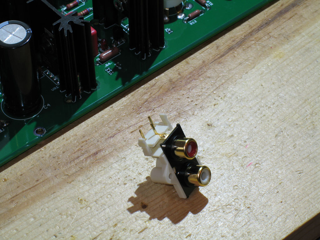
Step 22. - Install J2, the RCA jacks. Part of Dsavitsk's excellently refined design is the use of some PCB-mounted RCA jacks. I was suspicious at first, but these have worked out well on the prototypes and I sure am glad to not have to do any wiring!! Here's a shot of the RCA jack assembly - note the claw pins on both sides. You simply punch these into the outside holes on the J2 area of the PCB and then solder the three pins - Left, Right, and Ground:
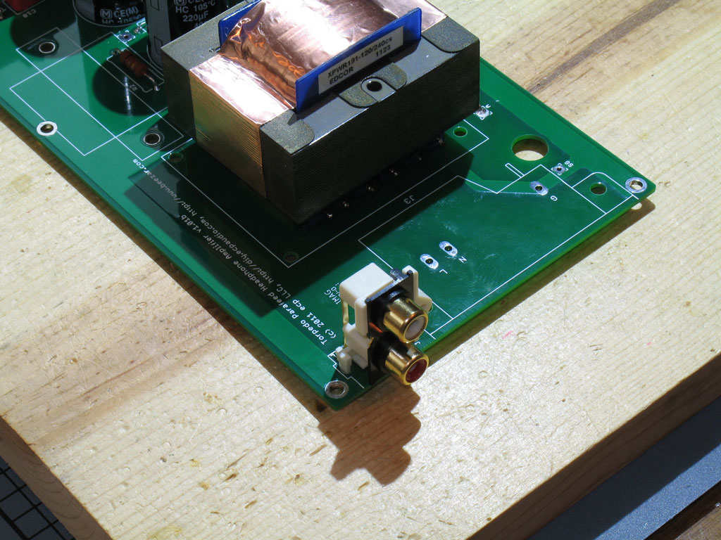
A shot of the RCA jacks with the claw pins snapped into place on the PCB (support the front of the PCB again!).
After applying solder to the three signal pins, here's where we're at:
Next - the IEC and we'll be done with the PCB! |
|
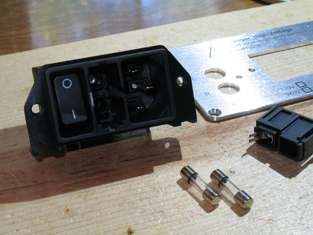
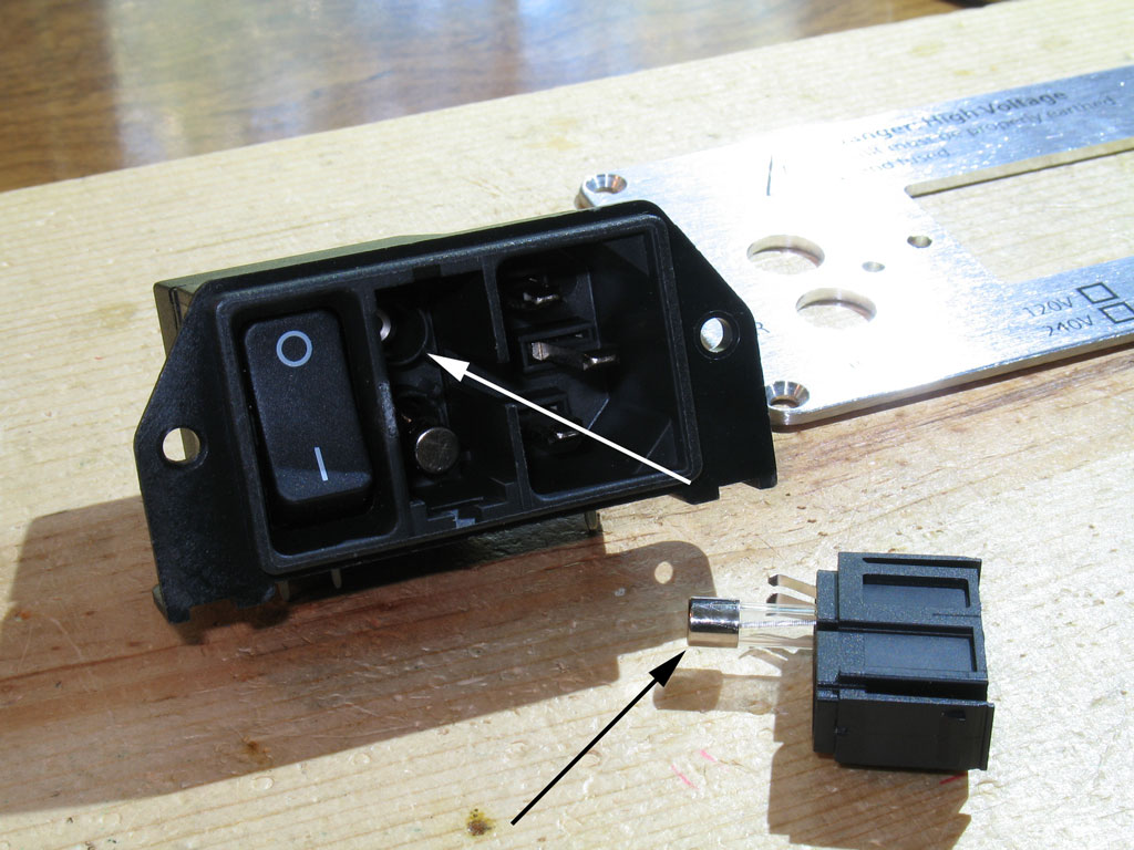
Step 23. - Next up is the IEC inlet! Pictured below are the 3 parts that make up the IEC inlet. Note that these must be ordered separately! (The custom case back plate is also shown.)
1) the IEC inlet and housing, 2) the fuse drawer, and 3) fuse and spare. To assemble the fuse drawer into the IEC, place the spare fuse either in the filter drawer or the IEC (in the IEC is shown):
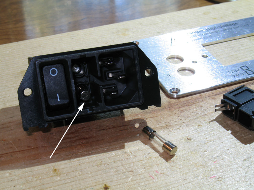
Next, place the primary fuse should be inserted into the fuse drawer (it won't sit in the IEC without the support of the fuse drawer):
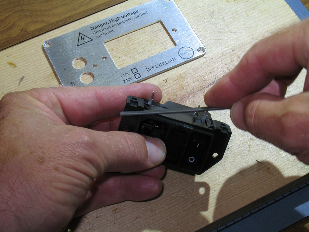
Snap the filter drawer in place. Shown below is the filter drawer snapped in place alongside the back plate:
Next we'll "snap" the IEC into the back plate and screw it into place. The reason we do this at this point - instead of simply soldering the IEC onto the PCB - is that there is some play, backwards and forwards, with the PCB and the case fit-up. This was done because all of the parts are essentially locked into place once soldered onto the PCB. Over a length of 14 inches, this can cause huge issues if the parts don't fit perfectly or are not soldered into place exactly in alignment. For that reason (and also because the solder leads on the IEC are so big), there is some play in the IEC leads, its pads, and its PCB screw holes (there are two of those). To account for this and lock the perfect alignment in place from front to back, we'll mount the IEC onto the back plate, first. Once that's done and it's bolted into place, then we'll solder the IEC - back plate and all - to the PCB. The custom Beezar/ECP Audio case design includes a rectangular opening with radiused corners for the IEC. This opening is machined perfectly for the IEC design drawings. Unfortunately, being a molded phenolic, there are variances in the rectangular area on the IEC. Because the entire rectangle is exposed without any sort of cover, frame or other finishing attachment, we left no tolerance gap on the back plate. As a result, some IEC's will probably fit snuggly without an issue. Others may need a slight bit of filing to fit. If yours doesn't fit perfectly (mine didn't on this build, either), wedge the IEC into place on the back plate as best you can. Hold the assembly up to a light and you'll easily be able to see where there's clearance and where's there is none. Remove the IEC and using a small flat file, file enough off of the high spots until you get it to snap in place:
After some slight filing (careful - it is very easy to file the plastic/phenolic!), we have a perfect fit:
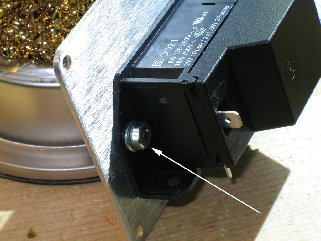
Now that it's snapped into place on the back plate, we'll screw it flush to the back plate using the familiar 4-40 screws, washers and nuts. Here's the view from the back with the screws in place and the IEC firmly mounted to the back plate:
On the inside, we finish off the cap screw assembly with a flat washer, a lock washer, and nut:
|
|
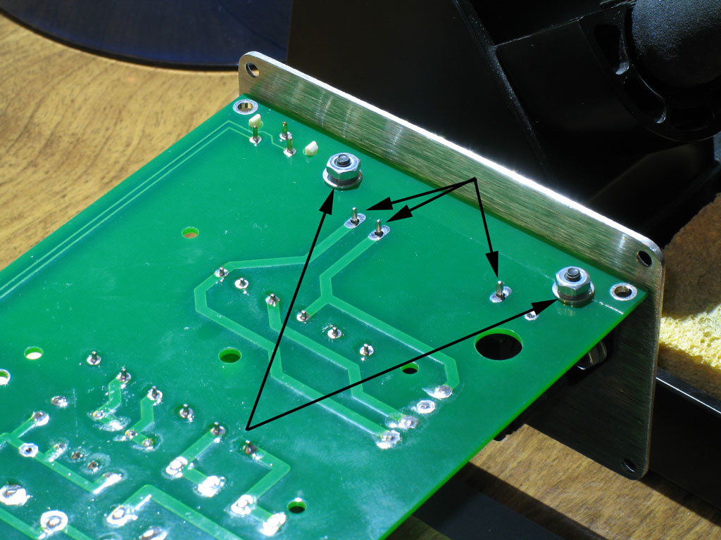
To install the IEC/back plate assembly to the PCB, we "roll" the IEC-back plate assembly onto the back of the PCB for preparation of soldering into place. There are several screw holes that need to be screwed down, first. Again, remember - once we solder it, there's no moving it again. So, we get the alignment correct and mount the screws, first. Shown below is one of the two screw mounting holes for the PCB - there's one on each side of the IEC inlet that screws it to the PCB. Also indicated is a single screw hole for the RCA jack assembly that screws the RCA jacks to the back plate.
Here we see the back plate around the RCA jack assembly. The RCA jacks actually have a concentric ring that's larger than the RCA jack barrels themselves. The holes in the back plate account for this, so be sure that the holes are fit around those larger rings and not mis-aligned ... before you screw the screw into the jack assembly. On the first couple of builds, I actually tapped this assembly for 4-40 threads. However, it turns out that the white plastic is soft enough that you can screw in a regular 4-40 screw and it will self-tap on its own. (You can see some of the plastic chips in the previous pic as a result of doing this.):
Finally!! Here we see the bottom of the PCB with the IEC pins (3 of them) ready to solder. Also shown are the screws that mount the IEC to the PCB (same flat washer, lock washer, and nut as used on all the other screws):
|


file last changed:Friday, December 30, 2011 6:00:00 AM
Please contact the TORPEDO webmaster for questions about these web pages.