www.beezar.com

|
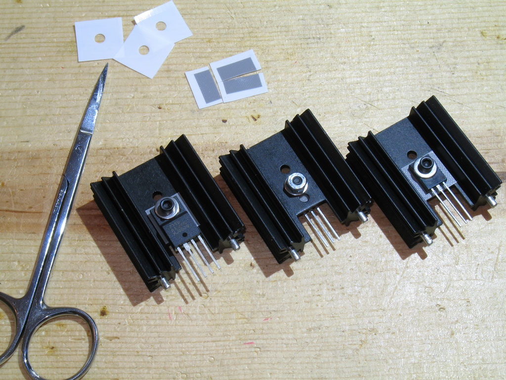
Step 18. - Next up are the large transistors and their heat sink assemblies. There are three - one each for the Left and Right CCS circuit and one for the heater supply voltage regulator. Here we see some heat sink kits and a couple of the 1-1/2" tall heat sinks that are recommended:
Note the VR1 heater supply voltage regulator. Each heat sink comes with three holes, so there's a decision that has to be made about which hole to use to mount the transistor/IC. The top hole leaves too little leads to solder into the PCB, while the lowest hole has the widest part of the leads below the top surface of the PCB (into the pads, IOW). So, the middle hole was chosen. The CCS transistors are not so straightforward in this decision. It's possible to locate them on the lowest hole, but that will cover some of the slot cutout in the heat sink (used for additional cooling by providing venting). So, the middle hole is chosen for those transistors as well, keeping everything consistent. Here are the three assemblies made up and ready to install on the PCB:
See the details on heat sink mounting on the Torpedo website. Essentially for each mounting, you have the following:
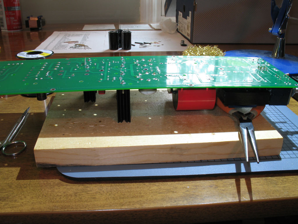
As noted before, those slots in the bottom of the heat sink are intended for additional cooling by providing a vent around the transistor. So, trim the thermal pads before sticking on so that they do not partially cover those slots. Also, like the car tire analogy mentioned above, you want these finger-tight, only. Wait until you get them soldered into the PCB before you torque down on the screws/nuts. Torque is probably too strong a word, though, because you want to tighten them so that the lock washer is obviously compressed, but not enough so that the thermal pads get cut. There is high-voltage going through the CCS transistors, so you don't want them shorting to the heat sink. Here we have them placed on the PCB, the PCB flipped over so that you can apply pressure to the PCB/heat sinks - ensuring a flush fit - and supported on the nose-heavy end. Notice the curve of the PCB, regardless:
Start with the transistor pins, first. Alternate from one pin on one transistor to another pin on another transistor, then repeat until all of the pins are soldered. This allows each transistor some time to cool while you're soldering the other two. When the pins are soldered, then solder one heat sink pin each. Flip the PCB over for a gut-check on alignment. If OK, then flip back over and solder the remaining pin on each heat sink. Here we see the heat sinks and their transistors completely installed:
|
|
Step 19. -
Next, we install the big caps - C2, C3, both of which are measly little 220uf, but the important factor is that they're 400V! Hence, their size.
C2 and C3 are the two caps pointed to with the arrows at top. Same-same with installation, turn over the PCB, make sure the end with the OT's is properly supported (or at least supported in some way), apply pressure while soldering to keep the caps flush with the PCB. Step 20. - Next up is the last cap - C4. This one is in in the heater supply, so low voltage, but lots of uf's - 4700uf and 16V. It's Step #20 because it's actually a bit taller than C2 and C3. Follow the same procedure described above to install:
Same photo, but C4 is the cap with the arrow at the bottom. |
|
Step 21. - Now comes the Power Transformer (PT), the big Kahuna! Pretty soon the PCB is going to feel and act like a giant barbell with lots of weight on the ends - ready to bend in the middle at a moment's notice. So, remember to minimize the torque on the PCB as you install the PT. Shown below is the PT next to the PCB:
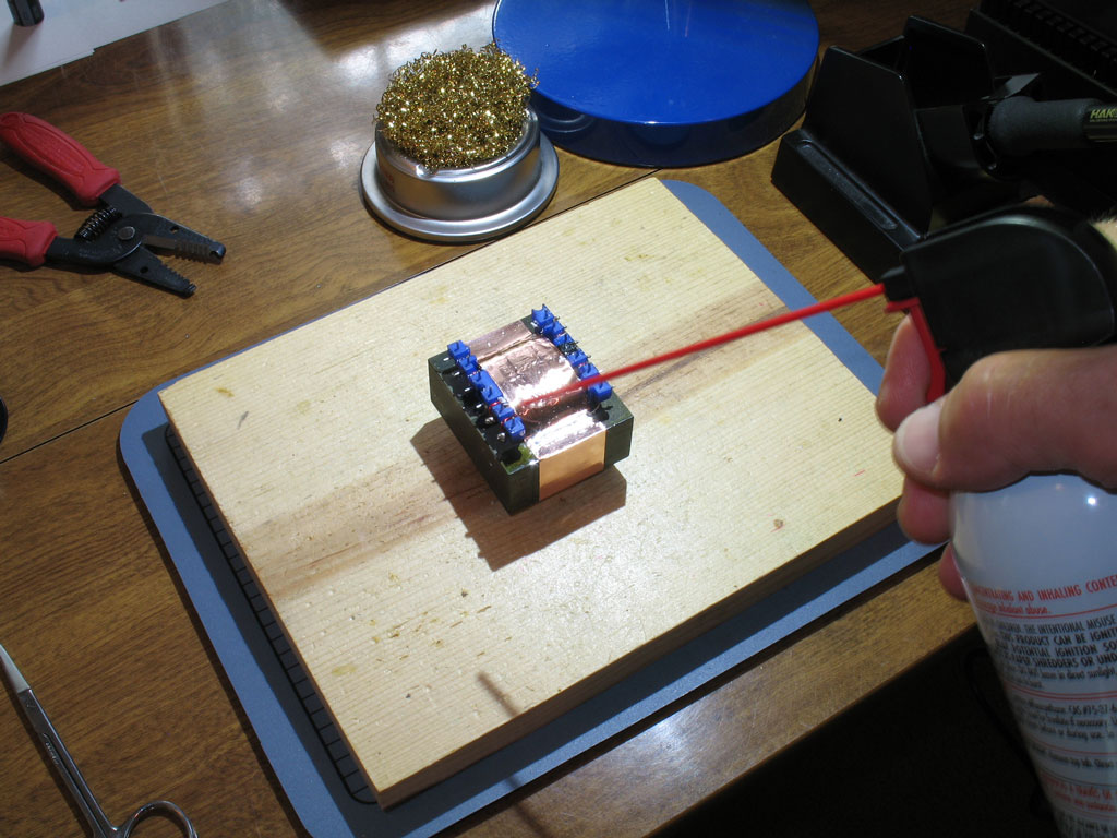
In a similar manner as the OT's, the PT is keyed with two pins on one end that are closer than the rest. Take note of those pins as shown in the pic, and place the transformer into the PCB pads accordingly. Also note that unlike the OT's, there are no plastic post spacers that will prevent the blue plastic rails from being flush to the PCB. That said, the there's a lot of windings and pins there and it may be too much to ask Edcor to keep those blue plastic rails perfectly flush. So, yes - you can get a large portion of the rails flush with the PCB, but probably not for their entire length. That's OK - just do the best you can. As with the OT's, the PT is packed in close-cellular foam when it was shipped from the factory, so there may little bits of foam caught in spaces between the plastic rails and elsewhere. This pic shows me using some canned air to blow out all of those foam bits:
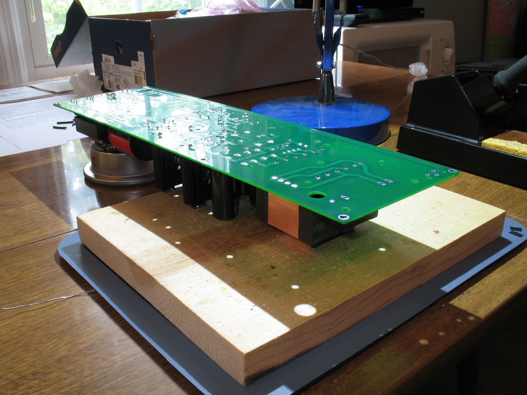
Here we see the PCB flipped over and ready for soldering the PT in place. As with the OT's, I placed the PT on the PCB with the PT's pins in the proper pads, place the pine building board on top of the PT, and then flipped the entire arrangement so that it was upside down as shown in the pic:
Be sure to support the OT's and the front of the PCB as shown. It would be a shame to try to solder with the huge curve that weight on the end will inflict on the PCB. That would probably end up popping some traces. So, use some caution and make sure the PCB is supported on the ends.
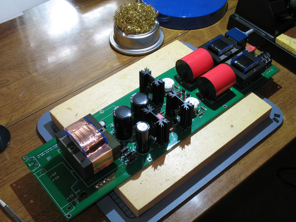
As with the OT's, the blue plastic rails will melt pretty easily if you leave the heat on too long. So, solder hotly and quickly, but not so fast that you might get cold joints. Finally, we see the PT installed and the PCB is now taking on a much more symmetrical look from front to back:
All that's left are the RCA jacks and the IEC inlet!! |


 I don't know about most of you guys/gals, but this was my first experience at large electrolytic, "snap-in" capacitors. My whole DIY career, I've looked for which lead was the longest on an electrolytic capacitor, and placed it in the pad marked "+". Unfortunately, the snap-in leads are short, thick, with a bend for "snapping" into the PCB, and most important of all - of equal length.

file last changed:Friday, December 30, 2011 6:00:00 AM
Please contact the TORPEDO webmaster for questions about these web pages.