www.beezar.com

|
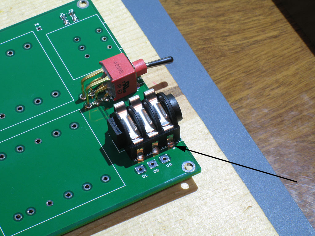
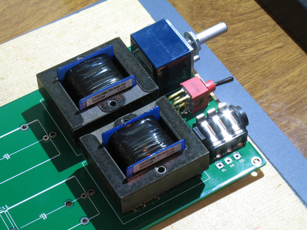
Step 14. - Install the headphone jack. This is pretty standard, as most of you should've installed a headphone jack before. However, please note earlier instructions to keep the parts flush against the top surface of the PCB and aligned. The Torpedo front plate has little play and there is no flexibility in adjusting the position of soldered-in parts.
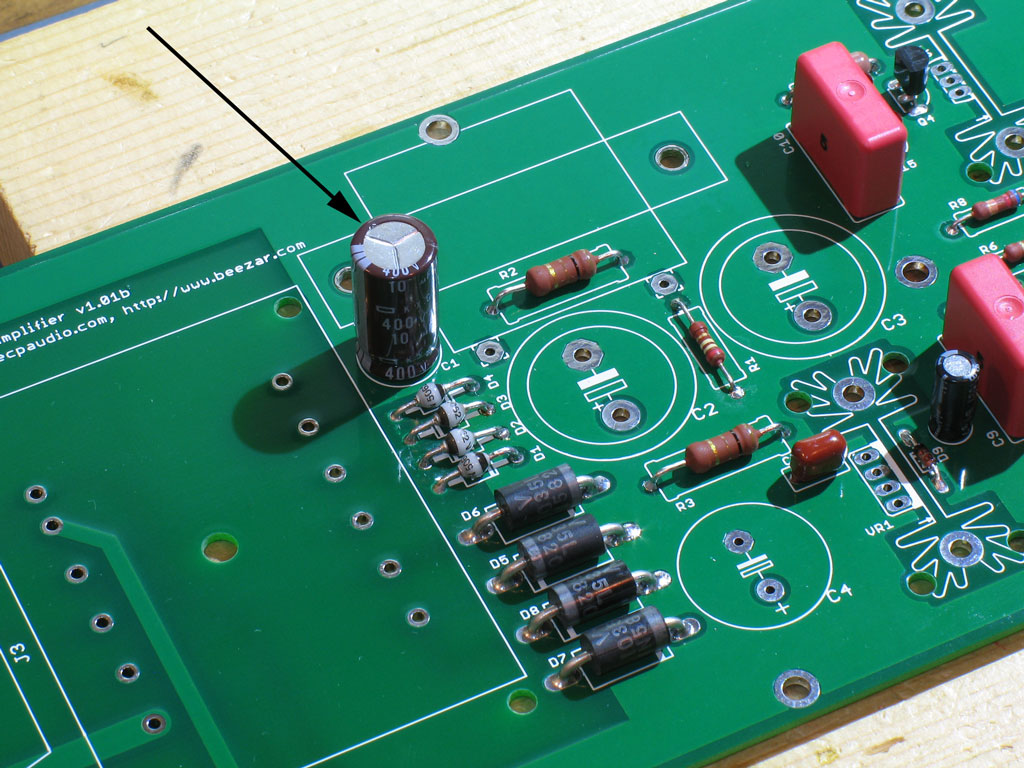
This is another mechanical-electrical connection, so again - try to make certain that the solder joints wick up the top side of the PCB and the headphone jack pins. If you have trouble with the ground pins (the ones in front indicated by the arrow), then solder some on the top side - but be careful! The body of the headphone jack is plastic and it will melt! Step 15. - Install the C1 capacitor as shown:
Step 16. - Install the Alps Blue Velvet pot (RK27). Be careful here ... the pot should be aligned so that the pot shaft is perpendicular to the front edge of the PCB. There is some play in the PCB pads. Solder one joint on the back side and then turn the PCB over. Check for pot shaft alignment. You don't want to have a crooked volume knob for the life of the amp. Use a draftsman's triangle, multiple eyeball views, whatever - just try to get it straight:
|
|
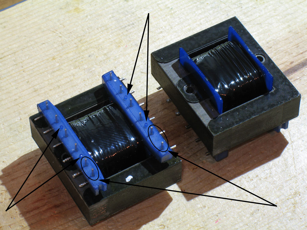
Step 17. - Next are the Output Transformers (OTs). These are custom-designed/specified by Dsavitsk and fabricated by Edcor:
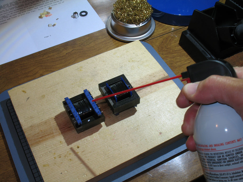
Note a couple of things here ... the pins on the left in the photo above are closer together than the pins on the other side of the transformer. This is what keys the transformers in place on the PCB. You can't get them in backwards unless you seriously force something into damage. Also take note of the plastic pins. When you go to solder the transformers in place, you will not be able to get them flush to the PCB - only the pins. So when you look sideways at the transformer and PCB, there will be a gap between the blue plastic skids and the PCB. This is normal. Prior to placing the transformers on the PCB and soldering them in place, give them a shot of compressed air or similar. The transformers are packed in closed-cellular foam and bits of the foam may get in-between the pins and/or the blue skids and the metal laminations. The bits of foam will stink to high heaven when you solder the pins (maybe a bad gas of some sort), so you'll thank yourself for getting them clean of the foam bits prior to installation:
Place the transformers in their positions on the PCB. Locate the two close pins highlighted in the first pic above, and place those in the two close pads on the PCB. I do this by placing them on the PCB, picking up and turning over the pine building board, placing it on top of the OT's, and then turning over the whole assembly so that it looks like the pic below. Both Left and Right channel OTs are the same. The only thing that differentiates the Left from the Right are the traces on the PCB. The pads are marked below. As noted previously, the transformer skids are blue plastic and they will melt. So, solder completely, but quickly. Alternate sides to keep one blue skid cooling while you're soldering the other one. Apply some decent pressure to the PCB so that at least the transformers are flush with the blue locating pins shown in the first pic above.
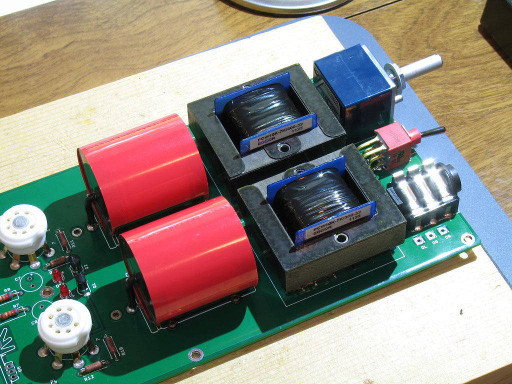
Once soldered in place, they'll look like this:
Note that the PCB assembly will be quite lopsided in weight after this. Please handle the assembly carefully from here until its finished. You don't want to bend the PCB too much or put a lot of torque on the traces underneath. Next up are the parafeed capacitors. I don't actually have this labeled as a separate step, because their position in the build sequence will vary considerably, depending on which capacitors you purchase. I used the Clarity SA caps (obtained from Madisound), which are some of the largest you can install in the Torpedo. So, their installation came after just about everything but the very largest parts.
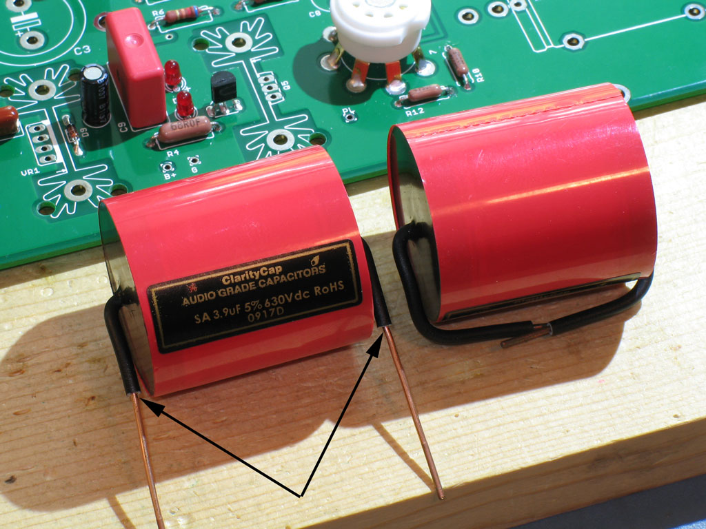
Note that the Clarity caps come with some pretty long leads. Trim/strip the insulation as shown so that the leads are exposed at the point where the cap will be flush against the top surface of the PCB. Place them in the most convenient pads (there are several to pick from, depending on the size of the caps) and solder in place. Here they are installed:
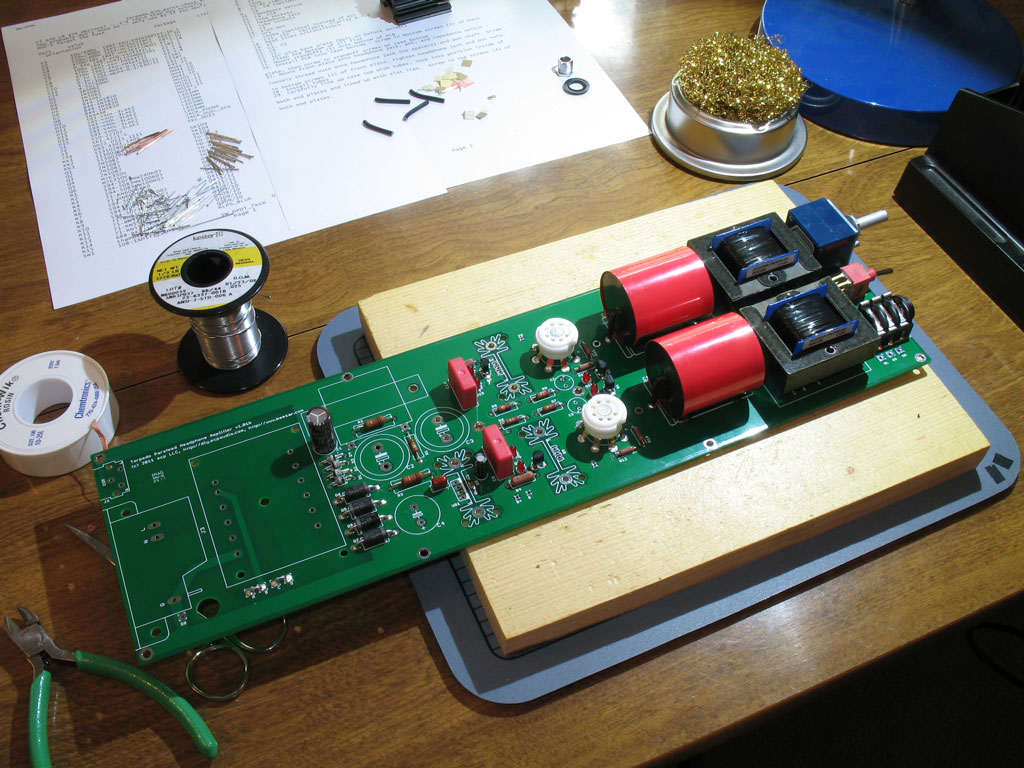
Just to give an intermediate perspective, here's a pic of a very lopsided assembly at the moment:
As noted previously, keep the PCB properly supported at this point and use caution in moving it around. Saying that it's nose-heavy at this point is a big understatement! |


file last changed:Friday, December 30, 2011 6:00:00 AM
Please contact the TORPEDO webmaster for questions about these web pages.