www.beezar.com

|
Step 3. - Install the High-Voltage rectifiers, D1, D2, D3, and D4. These are pretty neat little devils. They're encapsulated in glass. Again, the voltage they will be handling could be close to 300 volts, so please ensure that your solder connections are hot, clean and fully wicked to the top side of the PCB. As with the above, please turn the PCB over and add solder (and heat) as necessary to complete the ground plane connections on the top side - if needed:
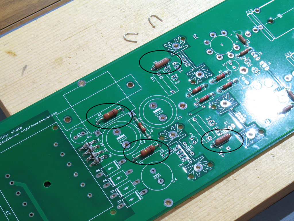
Step 4. - Install the higher-profile resistors - R3, R4, and R5. These are shown in the pic below:
UPDATE!!
Please install the Hammond #154H choke instead of using R2!
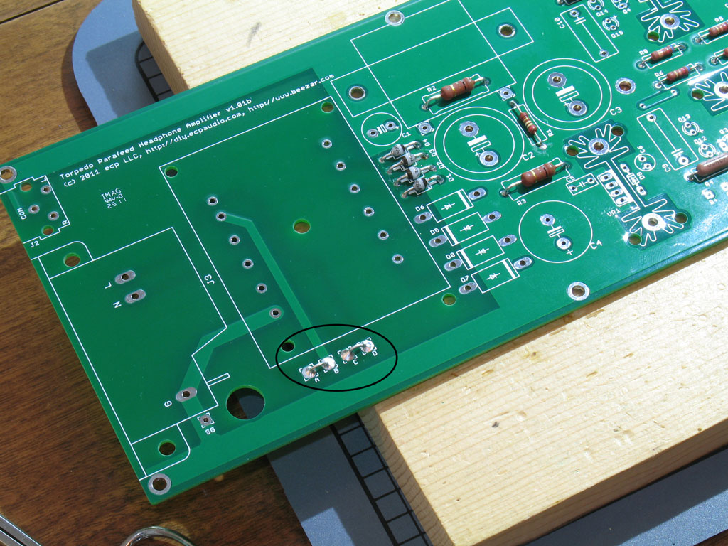
BTW, you will notice some jumpers at the top of the pic. We'll install these in Step 5. One might wonder, seeing as how the jumpers are just about as low a profile part as you can get on a through-hole PCB, why did we wait until Step 5? Simple - installing the resistors first gives us all of those spent leads that we can pick from to make the jumpers. At the same time, the board is long enough and the resistor parts are low enough that it doesn't create much of a problem installing the jumpers after the resistors. A note about R2: There is an option to use a choke at this position, instead. After the extensive prototyping we did, I think the general consensus is that the choke may have caused the introduction of some hum, so we went with the resistor option. You are welcome to try the choke - the opinions were far from conclusive and the resistor is an easy enough swap-out. On paper, the choke should be superior and it's possible that the hum/ripple came from the tubes. We've found that the 6J6 can operate seemingly fine, but can produce ripple if the tube is not completely up to snuff. So, your choice, but we'll stick with the resistor for this build. Step 5. - Install the jumpers for the power transformer. The power transformer is made to use either 120V or 240V input. For 120V, simply jumper "A" to "B" and "C" to "D." This is shown in the pic:
Again, good solder joints are called for and be sure you get wicking to the top side. Remember that this amp uses high-voltage. Build correctly and cleanly, you will never have an issue. BTW, international folks who will use 240V input will solder "B" to "C." |
|
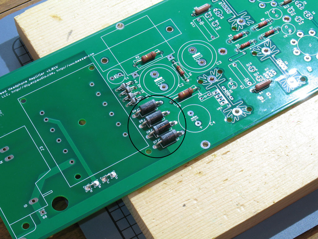
Step 6. - Install the Low-Voltage rectifiers - D5, D6, D7, and D8. These form the basis of the heater supply and while the eventual voltage is only ~6VDC, the current for two 6J6 tubes is quite high. Hence, the use of the large, Schottky barrel rectifiers. Those of you who've built a MiniMAX or MOSFET-MAX are probably familiar with these. Straightforward in installations, bend the leads and solder them in place:
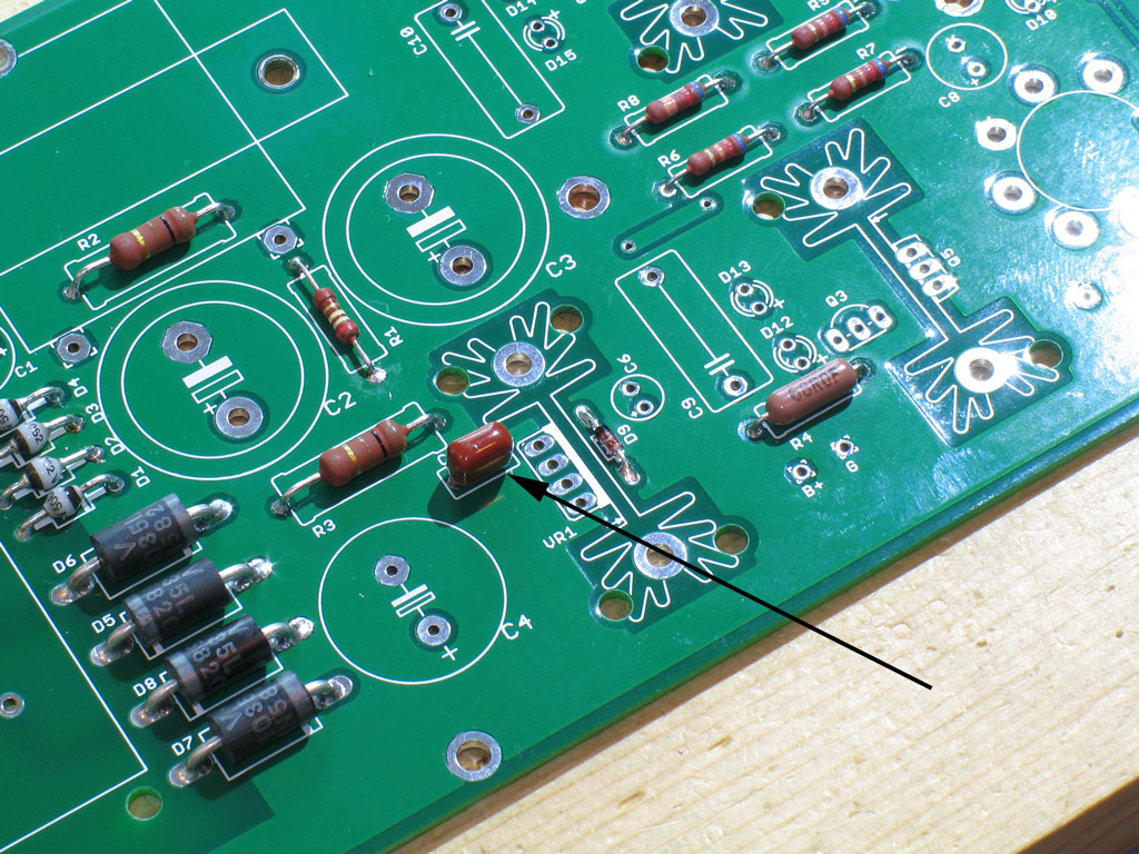
Step 7. - Install the C5 capacitor. No polarity is needed on this one:
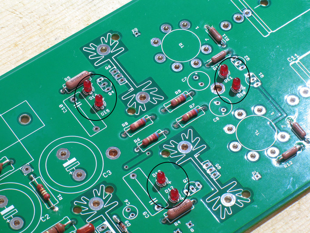
Step 8. - Install the LEDs - D10, D11, D13, and D15. No, these aren't tube lights. Dsavitsk uses a fairly unique solution with LEDs forming the basis of both the CCS (Constant Current Source) and Tube Bias. Both of these will be explained in detail on the Torpedo website, but suffice to say that not any 'ol LED will work. The proper LEDs are still plentiful and cheap, but any substitution must be carefully researched for the proper voltage/current relationship. We recommend you stay with the specified LEDs unless otherwise noted. Install with the long lead in the pads marked "+":
UPDATE!!
Please install the Zener Diode Tweak for D12 and D14. Refer to the Tweaks section for details.
|

file last changed:Friday, March 15, 2013 7:00:00 AM
Please contact the TORPEDO webmaster for questions about these web pages.