www.beezar.com

|
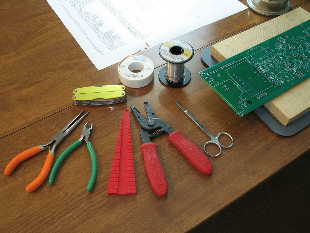
The Torpedo is fully PCB-based with no wiring needed, save a ground wire for the Alps pot and a safety ground wire from the PCB to the case. It uses readily available components, including tubes that run about $2 and less (6J6 - the 6V heater version of the Starving Student tubes). The only exception to that are the custom power and output transformers and a custom-designed case that requires no drilling/cutting. (BTW - most tube dealers say the 6J6 runs into the tens of thousands in stock, so no running out as happened with the 19J6 on the Starving Student.) Pictured below you see the PCB. Yes, it's long. It was done that way to get the power transformer as far away as possible from the output transformers - to reduce any tendency toward hum.
You can also see above, some of the tools that I use to populate a PCB -
Some of the other tools I use when soldering a PCB:
Your tools may vary, but I find these pretty much cover all my needs for most PCB's. |
|
The full building sequence will be posted on the upcoming Torpedo website, but generally speaking, it follows the standard lowest-to-tallest-part construction sequence.
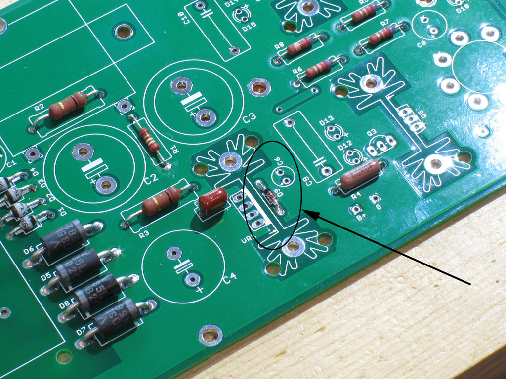
Step 1: Install the lowest profile electronic part, the D9 diode. (The BOM on the upcoming website will fully detail each part.) I actually made a mistake and forgot this until later on in my build, but it should be first:
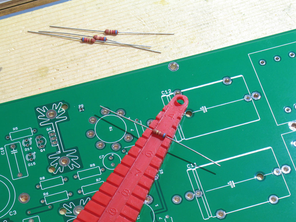
Step 2. Next, install the low-profile resistors. These include R1,R6,R7,R8,R9,R10,R11,R12, and R13. The Torpedo PCB was designed to make the greatest use of available parts, so the pads are larger than the standard resistors spec'd in the BOM. I find it helpful in those cases to use a lead-bending jig as shown here:
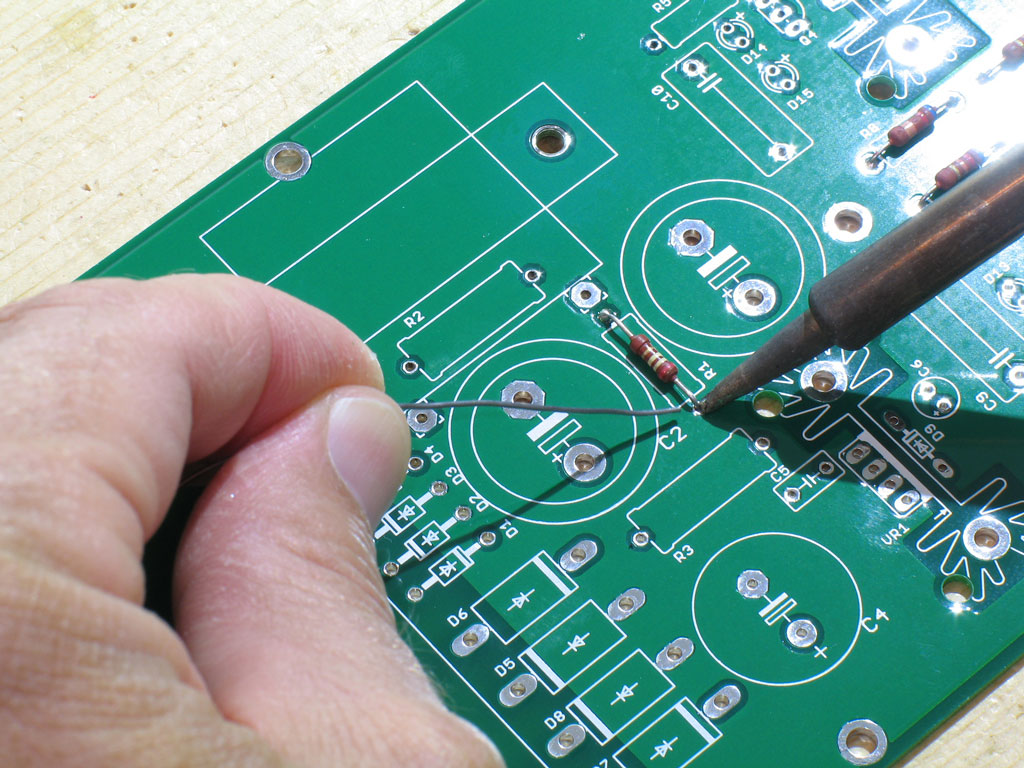
Next, place all the resistors - with their leads bent - in the proper locations and solder into place. This is straightforward and no different than any other design. However ... since the Torpedo PCB uses heavyweight 2oz. copper for the ground plane and the fact that it is 14" long in one direction, you may find that the ground pads have a tendency to "sink" the heat from your solder tip pretty quickly. IOW, you may have some difficulty in soldering the ground pads. That's OK - the holes are all through-plated. Nevertheless, due to the high-voltage characteristics of the amp, I recommend that you ensure proper wicking to the top side of the PCB for all joints. If necessary on the ground plane pads, please turn the PCB over and add additional solder as needed to ensure a good connection to the ground plane:
And here we have all of the low-profile resistors soldering in place:
|


file last changed:Friday, December 30, 2011 6:00:00 AM
Please contact the TORPEDO webmaster for questions about these web pages.