www.beezar.com

|
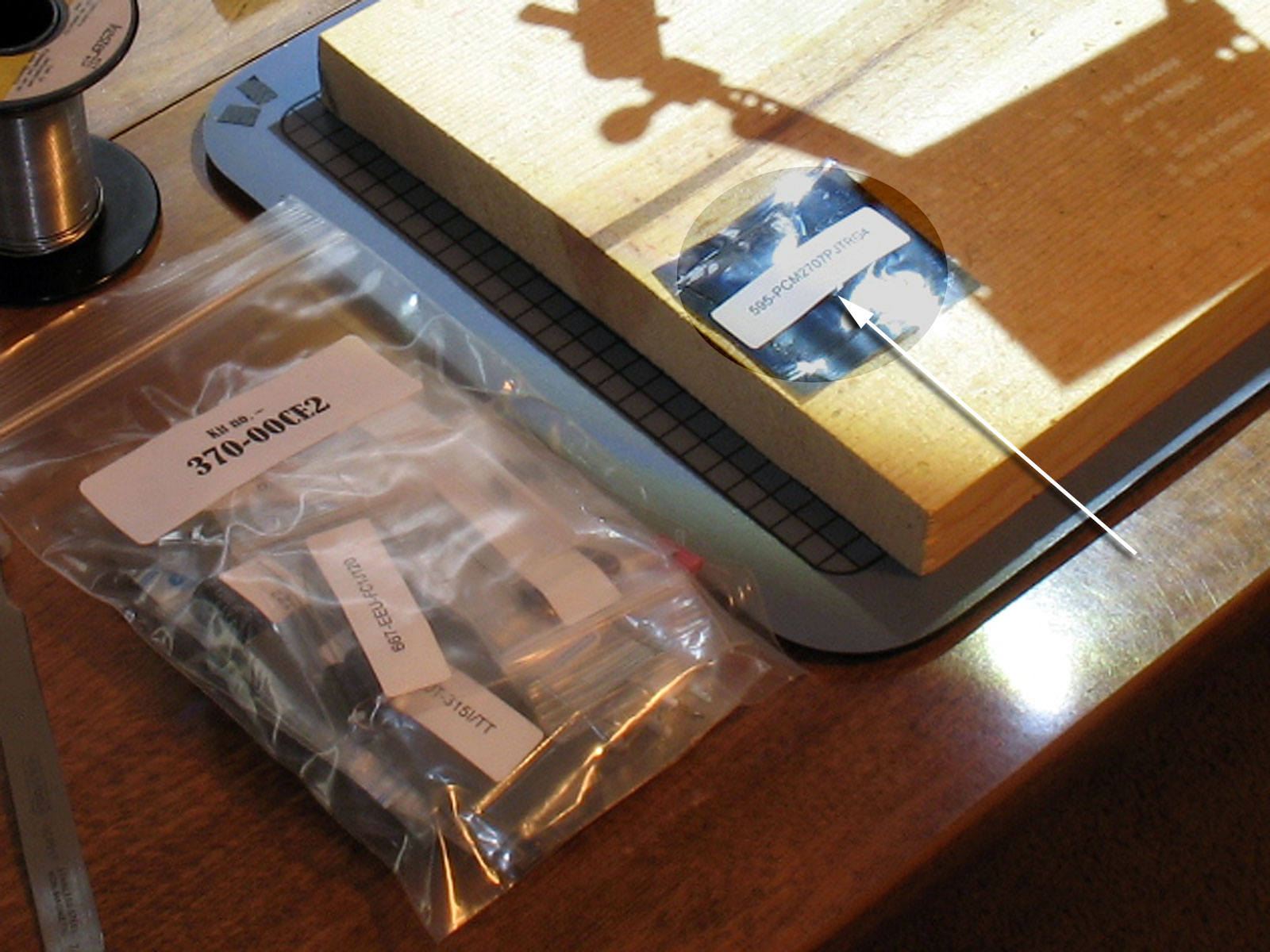
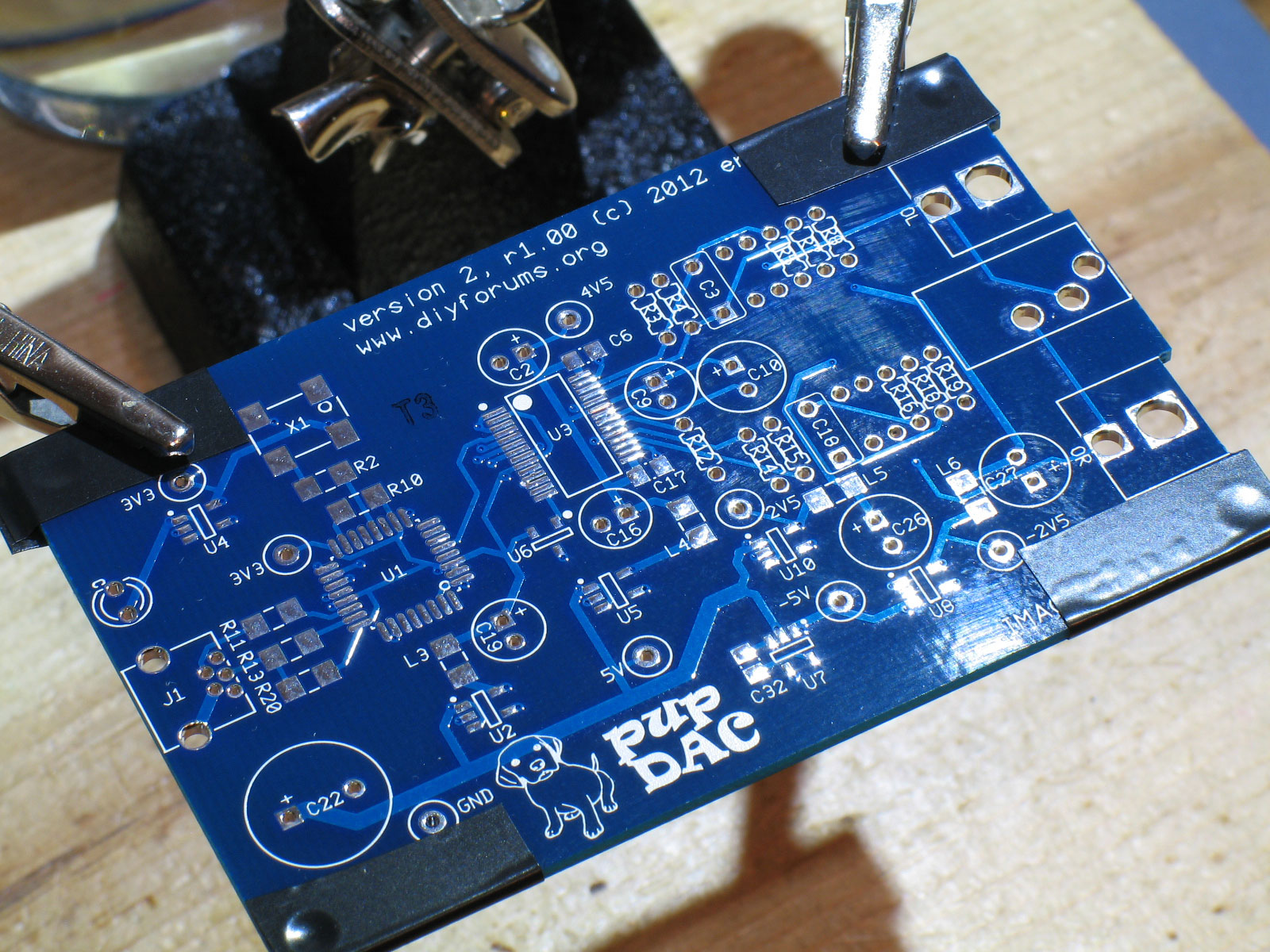
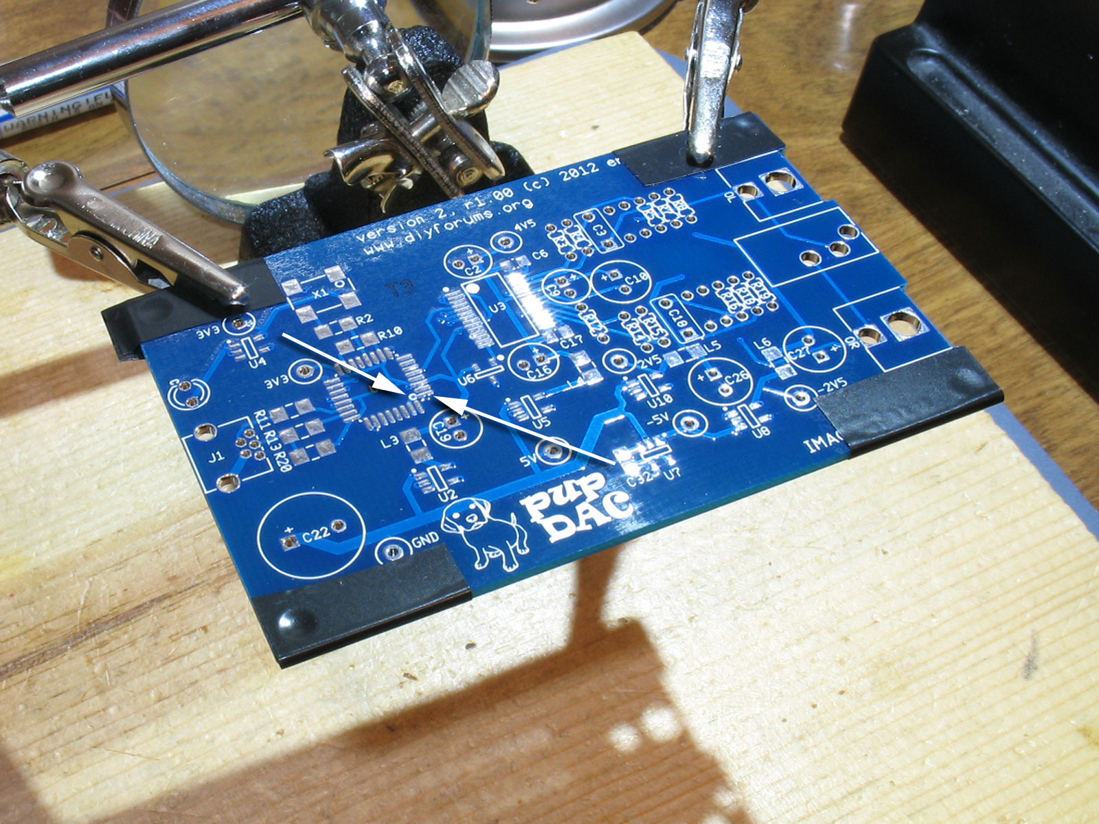
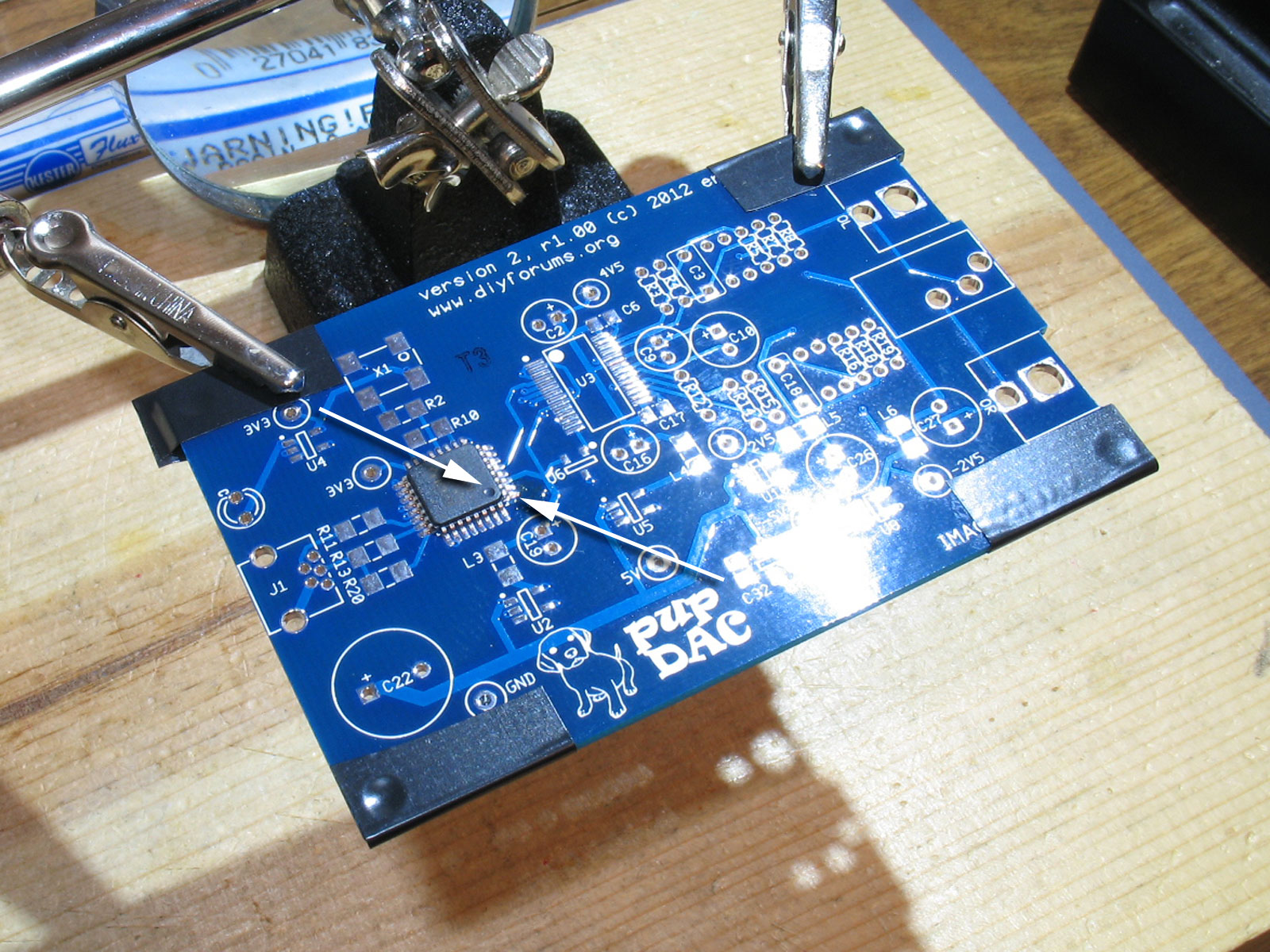
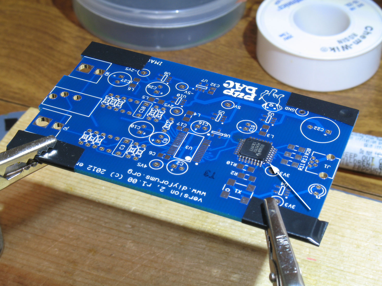
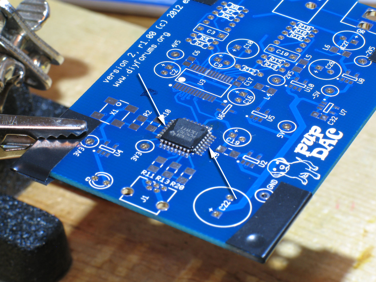
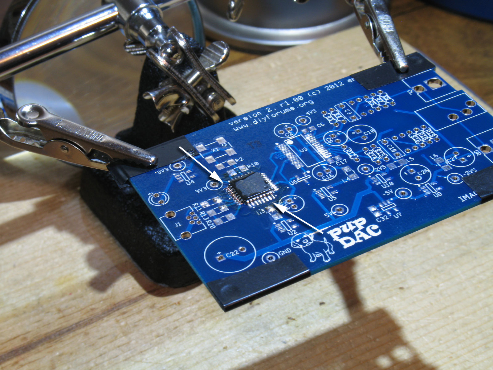
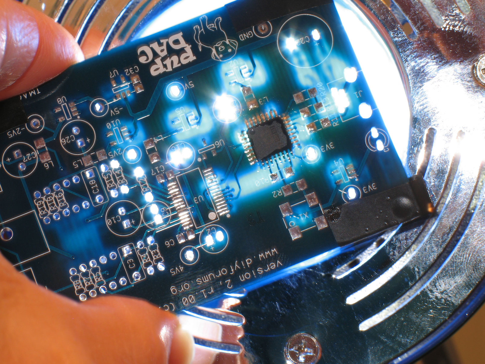
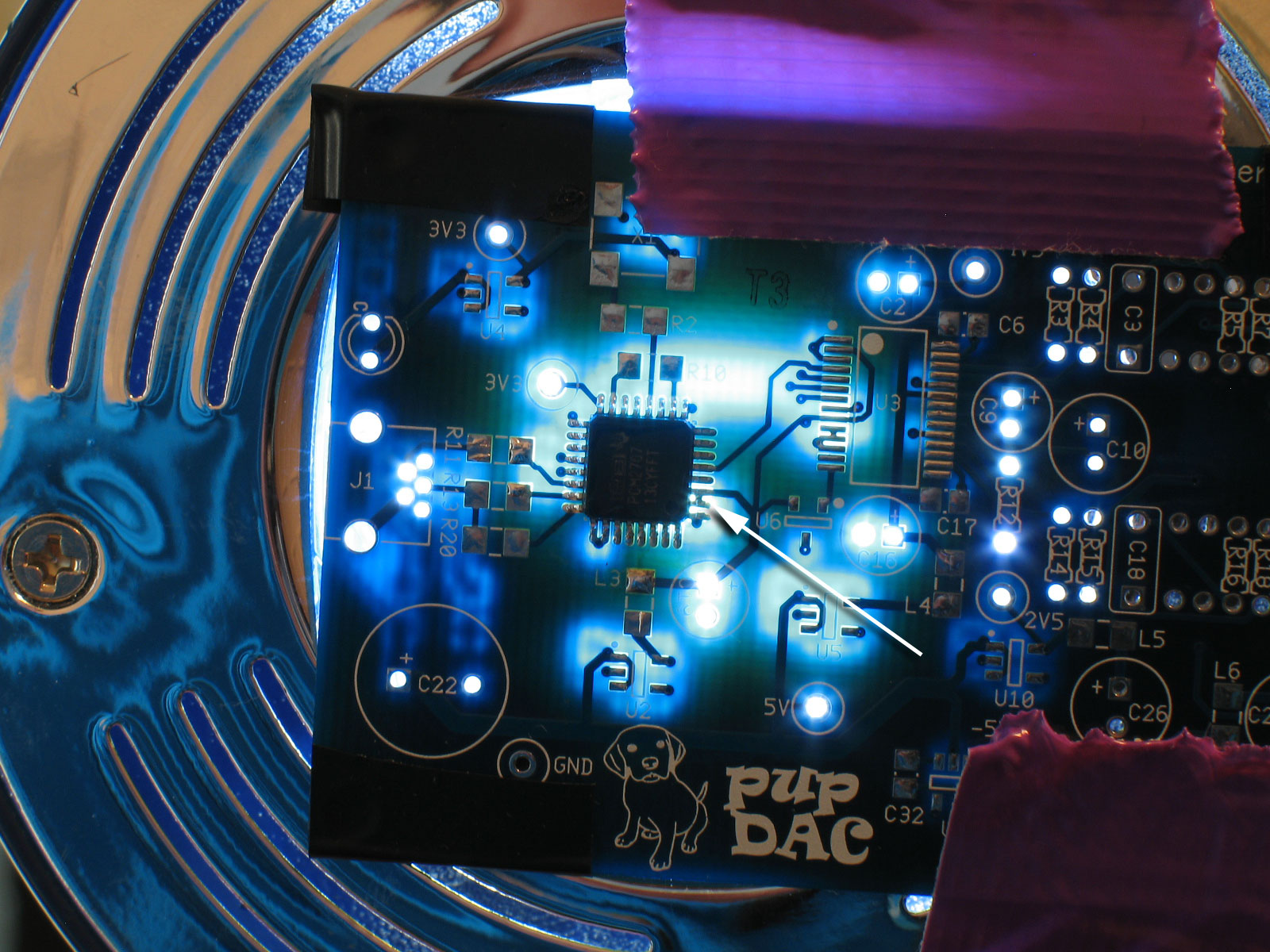
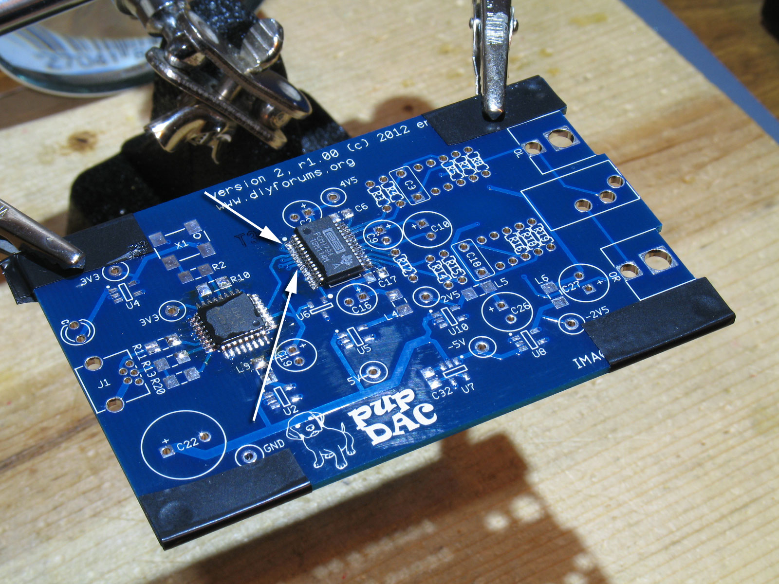
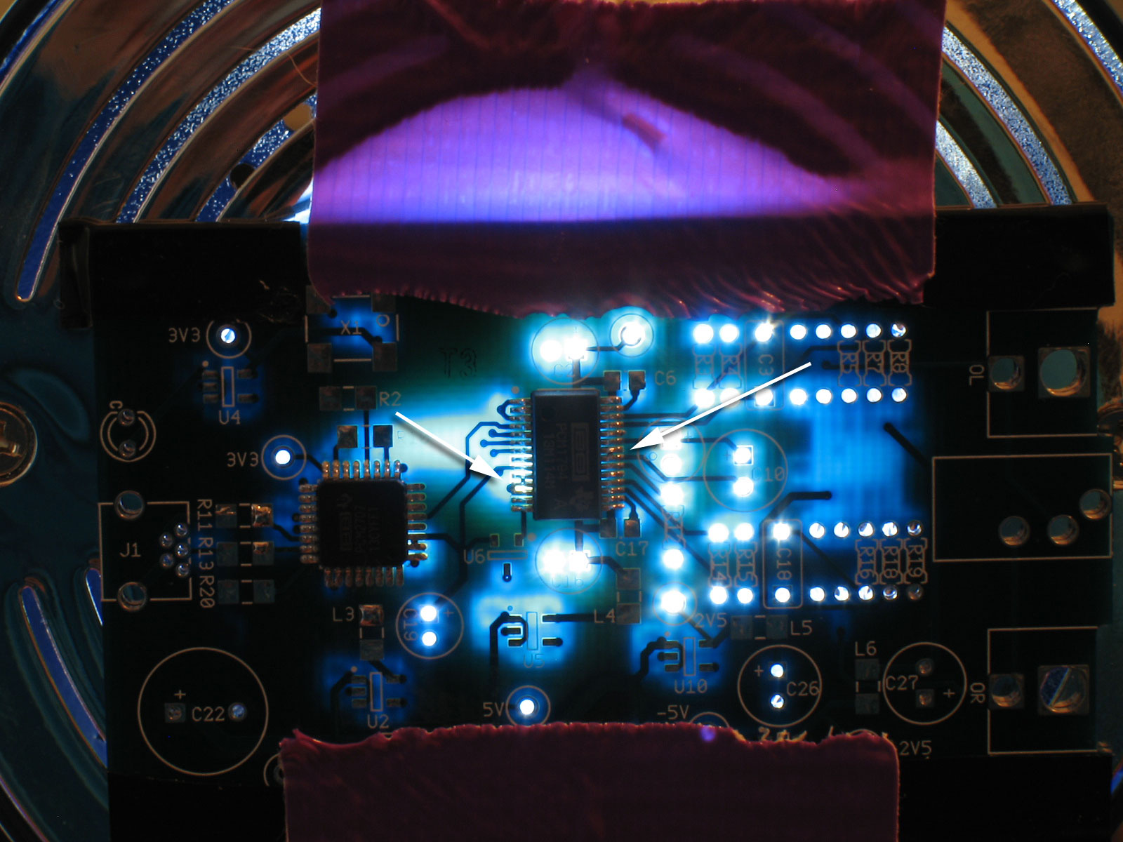
The first chip that needs to be installed is U1, the PCM2706/7 (both the PCM2706 or PCM2707 will work). Why this chip first? Because its pins are on all four sides (TQFP-32). You need clear access to all four sides to solder it properly. Once you add a single other part to the PCB, this will become harder. We hope you use the Mouser-produced kit, but keep in mind that the parts are not labeled according to the BOM and the PCB. They are all individually-labeled, but with Mouser's part number, not the pupDAC's: Here we see the pupDAC PCB again (smudges notwithstanding). It's held in the helping hands with alligator clips and electrical tape on all four corners for protection. Note the "T3" stamp. The pupDAC PCB's have been electrically tested at the manufacturer (Imagineering). No shorted trace defects to confound your build trouble-shooting. The first thing we need to do is prepare an anchor point for U1: If you get tired doing this, that's OK. Remove the tweezers and the soldering iron. Take a deep breath and relax. Try again by getting a grip on the chip with the tweezers and then applying the soldering iron to melt the pad again. Try to position the chip as good as you can - it will make the soldering much easier later on. Plus, you only have one bit of solder and pad to worry about in this step, so you can keep re-trying as much as you want. Even then, if the chip is a little rotated, you can actually twist it slightly on the PCB when the solder is cooled. Just work with it as long as you need to get it in the right position. Here we see U1 in place. One arrow is pointing to the soldered pad (the only one right now). The other is pointing to the alignment dot on U1. It's in the same position as in the pic above on the PCB silkscreen. If you're happy with the positioning of U1, then what we need to do next is to solder an opposite pad, locking U1 into place: Now that we have two pins soldered, locking U1 into place, we'll proceed with soldering all the rest of the pins: Bottom line, with the tools I've outlined above, you can actually solder each pin of U1 individually if you'd like. There's enough space to do this if your solder is on the order of 0.025" dia. and you use the small chisel point that I specified above. If not, you can use the drag and wipe method (my preference) or the method that you prefer. I like the drag and wipe because with the extended pads, you can literally solder every pin on the edge, removing the chances of bridges except at the very tip of the pins, where they're easy to access. Here I've turned the PCB around again, applied flux to the other two rows, and soldered them in place. Take a break and use the time to fully inspect your handiwork. We're going to all of this trouble, remember, because if you get U1 and U3 (the two PCM chips) messed up, your experience with building the pupDAC will not be a fun one. I'm holding the PCB up to a very bright light to check for soldering bridges: My hand got tired, so I decided to tape it up there. That way, I could check for bridges at my leisure. A good way to do this is to reference the PCB photos here on the pupDAC website. Note that the arrow is pointing to a "bridge" that's actually a connection of the traces on the PCB. It is not a soldering bridge. Next up is U3, the DAC chip itself (PCM1794). This chip is SSOP-28 and relatively expensive (almost half the price of an entire grubDAC kit!). Nevertheless, it is exactly the same chip form as the PCM2702 that was used in the Alien and BantamDACs, and the PCM2704/5 chip used in the SkeletonDAC. So all techniques and methods you may have used for those chips apply exactly!! Just as with U1, the first thing we want to do is apply solder to a corner pad and use that to position and anchor U3 into place on the PCB. As with U1 above, grab the U3 chip with your tweezers. When you have a good grip on it with your left hand, grab the soldering iron with your right and hold it to the bottom right pad on the PCB. While the solder on the pad is melted and holding the soldering iron in place to keep it melted, move the U3 chip into position so that its bottom right pin is applied to the pad with the melted solder. Try to align the chip so that the pins match up exactly with both rows of pads. Try to also position the chip so that there's a bit of clearance on both sides and portions of pads to the outside of the pins on both sides. As with U1 above, you only have a single pad with solder on it to worry about. So take your time, get the chip anchored so that it's aligned. As with U1, even after the solder has cooled on the anchor pad, you may be able to twist the chip slightly on the PCB to give a final alignment. Use a combination of both so that you have it aligned as good as you can get it. I didn't show it, but I flipped the PCB around to get better access to the top left pad as the second anchor point. Again, I use the drag and wipe method, but I throw some of the other soldering rules out the window. The pins are too small and too close together to solder individually, but maybe some of you will be capable of doing that. For me, after doing a number of these through the years, I CHEAT. Aligning the soldering iron parallel to the row of pins I'm going to solder, I apply a small (very small) bit of solder to the tip of the iron. Then I apply it to the pins - on the outside tips and pads. I may solder two or three pins at a time this way, finishing up with a drag and wipe to clean the excess solder that may result ("rinsing" the iron in the brass wool each time before a drag and wipe). So in effect, I'm applying solder to the outside of the pins, starting at top, and moving down 2 or 3 pins at a time. Trying to heat the pads/pins with the soldering iron and then to apply the solder to the heated pins, just doesn't work for me. Instead, apply solder directly to the iron, and then carefully to the pins (on the outside tips), while moving the iron down to the next set of pins at the same time. Think of it as a paint-by-number painting and instead of dipping a brush into paint, you're applying a tiny bit of solder to the tip of your soldering iron - then applying it to the "canvas". Some of this is redundant, but I hope I'm getting the idea across. Once you've made it to the bottom of a row, then finish it off with another couple of drag and wipes. If you see some pins that look "dry," apply a tiny bit of more solder to the tip of the iron and try again. Finish up with another drag and wipe. Use the brass wool each time before you drag and wipe. The iron will be clean after the brass wool and will actually pick up some extra solder that could form bridges. Not only does it give a better appearance to the soldered pins, but the drag and wipe method also serves to clean up excess solder. Here we see both rows of pins soldered: Take another break to inspect your handiwork. Make certain that these chips are soldered correctly before proceeding with the rest!! That cannot be emphasized enough! Get these chips right and the rest of the pupDAC is pretty straightforward. Let's use the light trick again: When you are satisfied that you've got these chips soldered OK, then proceed on with the rest of the build. |