www.beezar.com

|
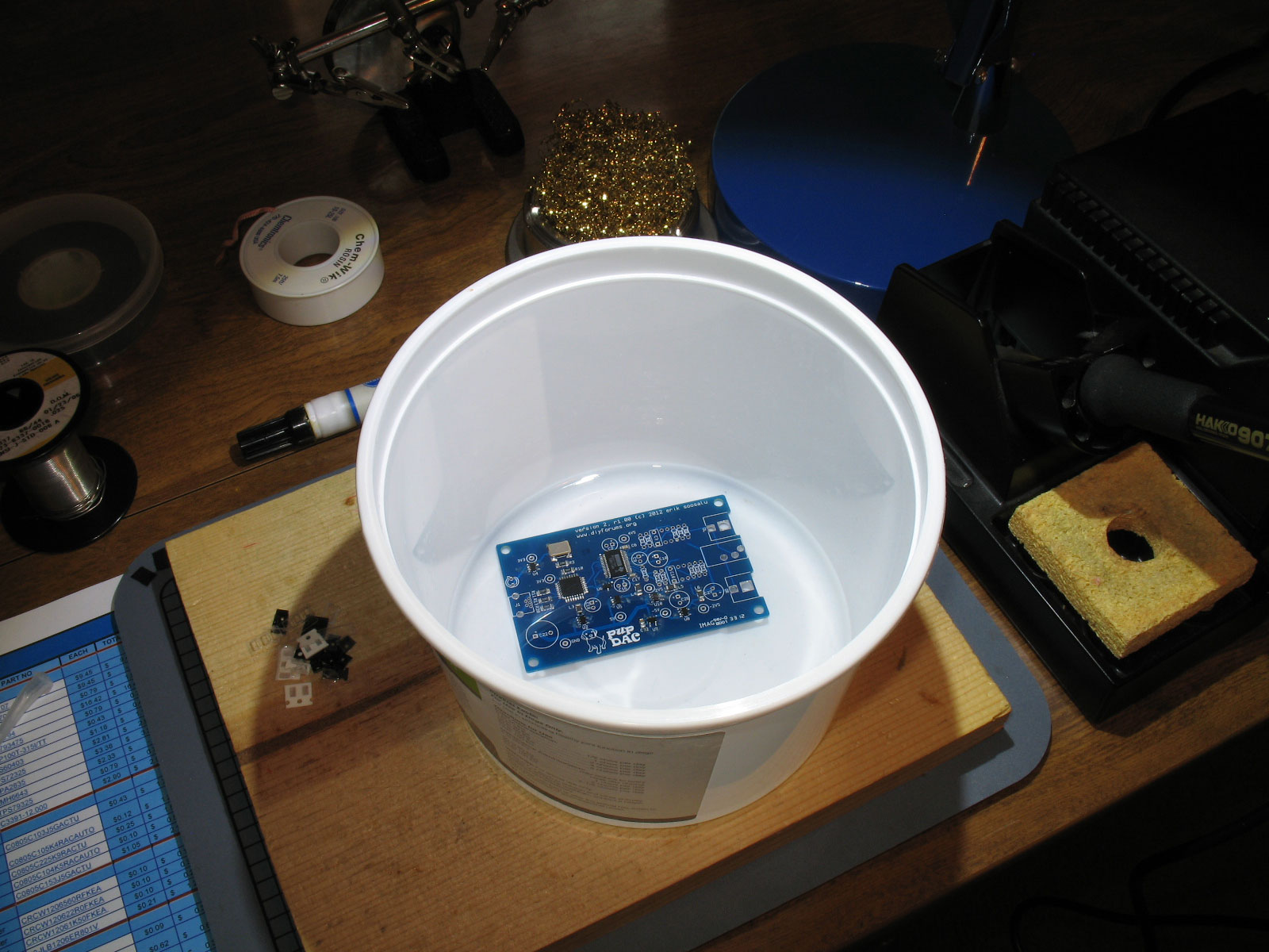
I like to clean everything up at this point. Why? Because the SMD parts can be immersed completely, whereas through-hole electrolytics are not completely sealed and could be hurt by doing this. At any rate, it gets things very clean among all those tiny pins. Wait till later and you may have all sorts of trouble getting things cleaned. I use 91% isopropyl alcohol from Walmart for cleaning all my projects. It leaves no residue once the board is completely rinsed and it readily dissolves flux. The use of an old toothbrush can help to get those troublesome flux patches off where the simple soaking does not. One thing to be aware of - the latest chips from TI use a different case material and is actually hygroscopic. The pins are sealed at the case body, but the body itself may absorb moisture. This is nothing to worry about except when you've rinsed at the end and you're ready to plug it in - don't. Wait for a few hours, use a hair dryer, put the PCB out in the sun, etc. to make certain that things are dry under and inside the chips. Otherwise, you'll drive yourself crazy trying to figure out why your DAC doesn't work or seems to de-activate itself every few minutes. On to the through-hole parts!
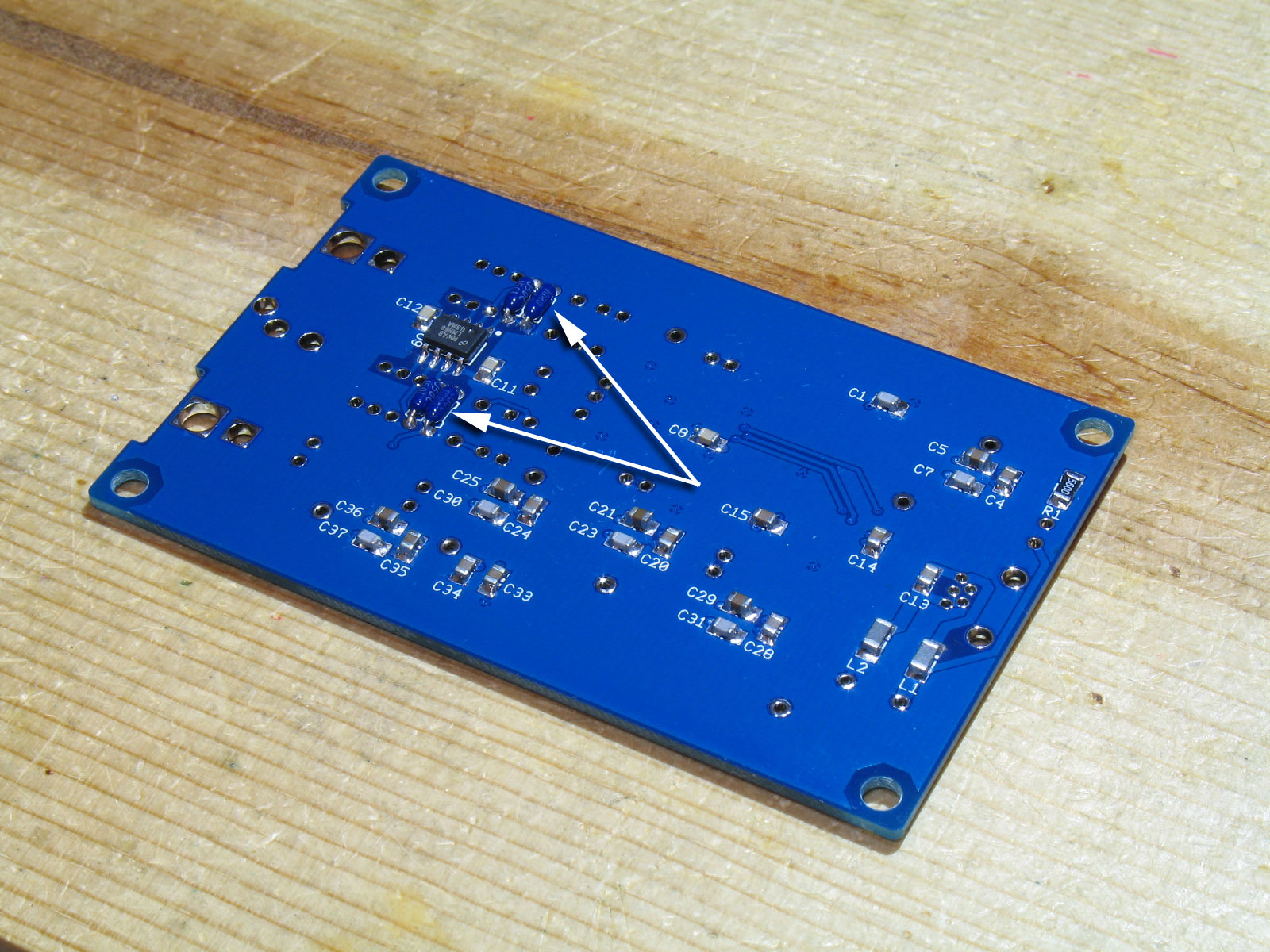
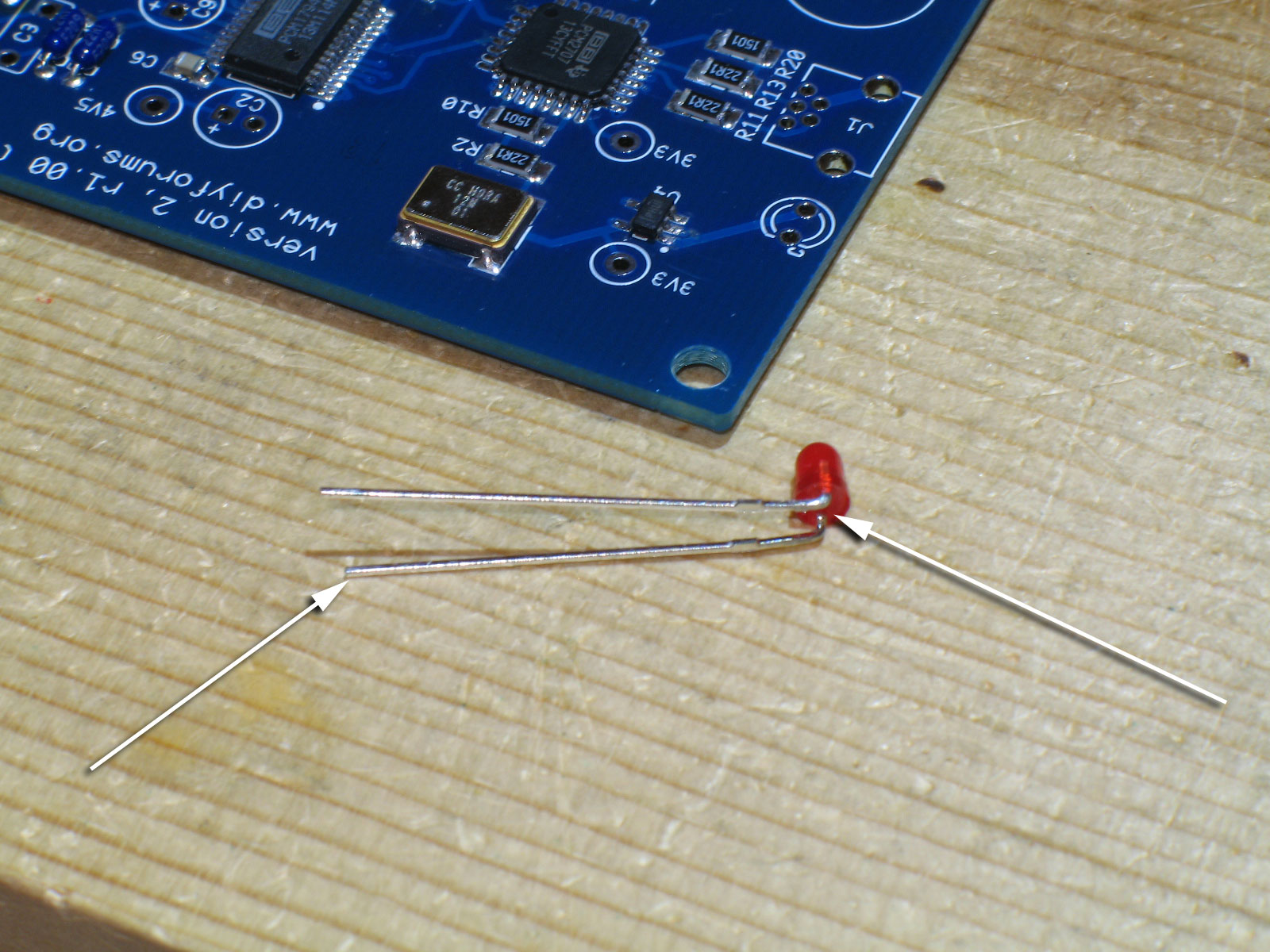
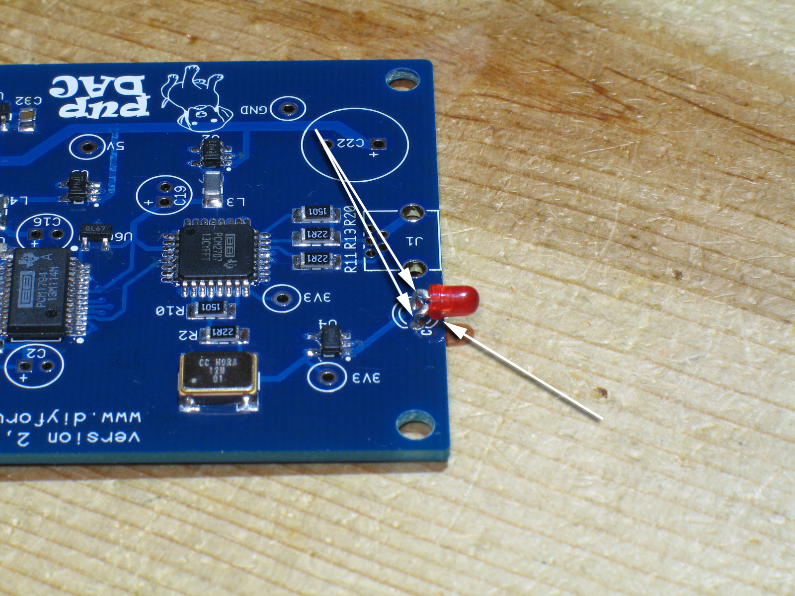
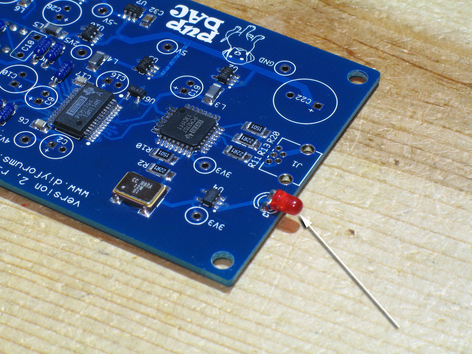
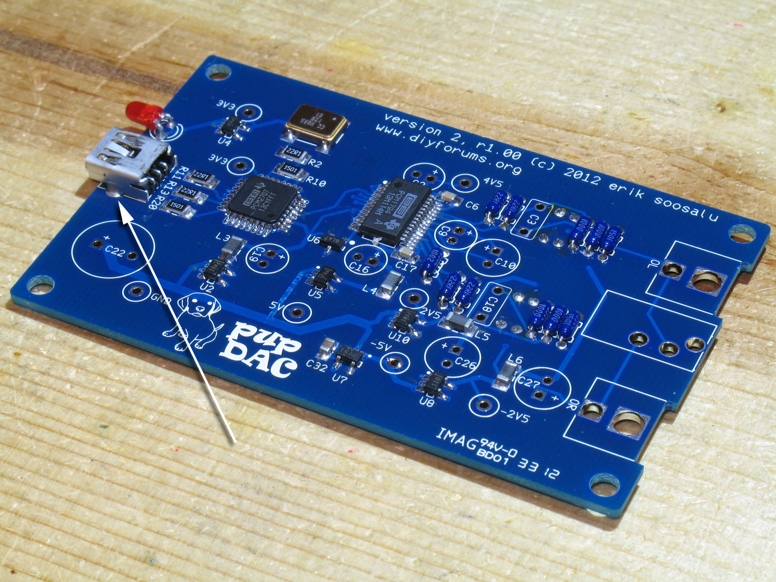
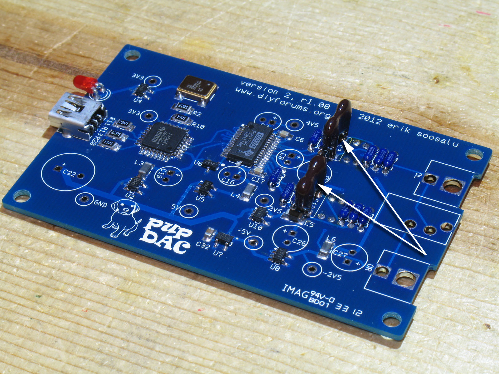
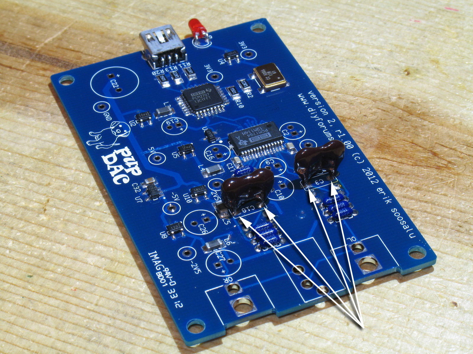
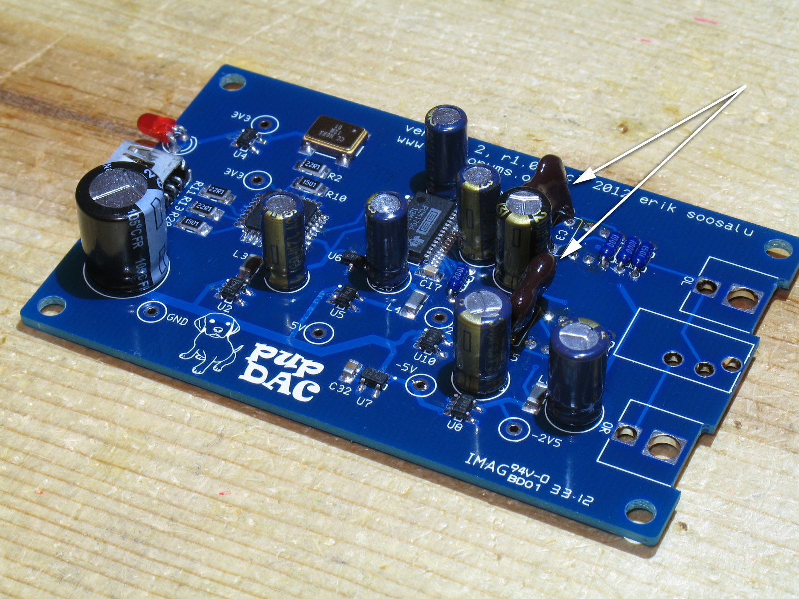
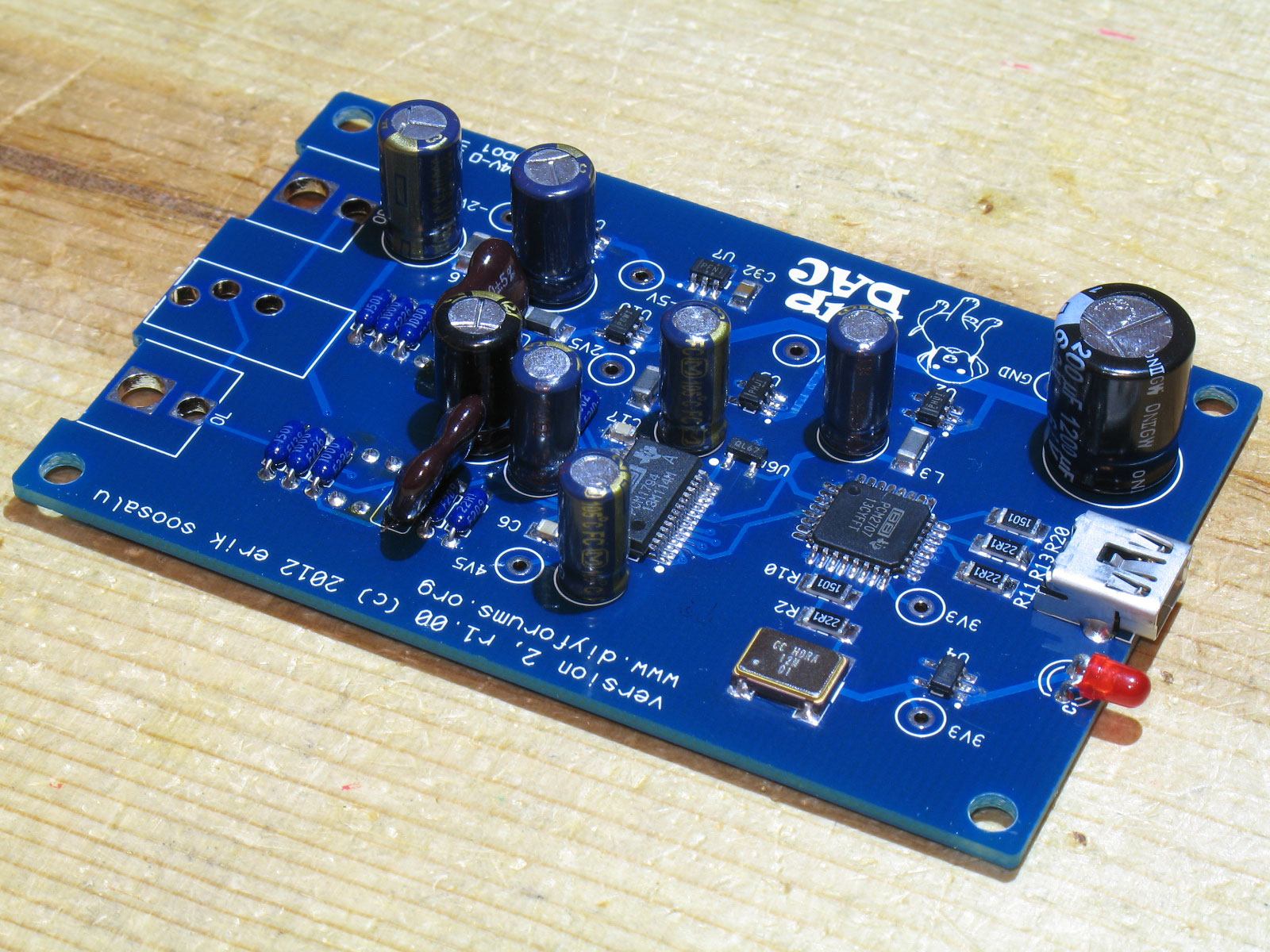
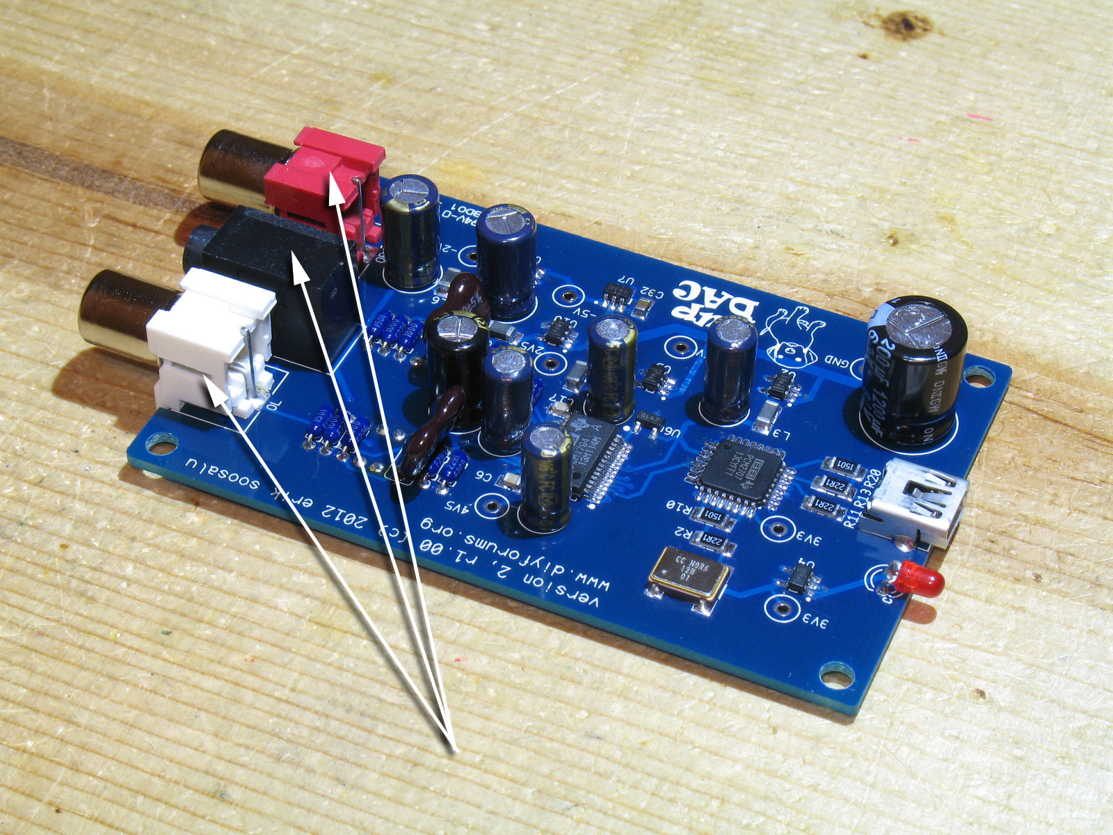
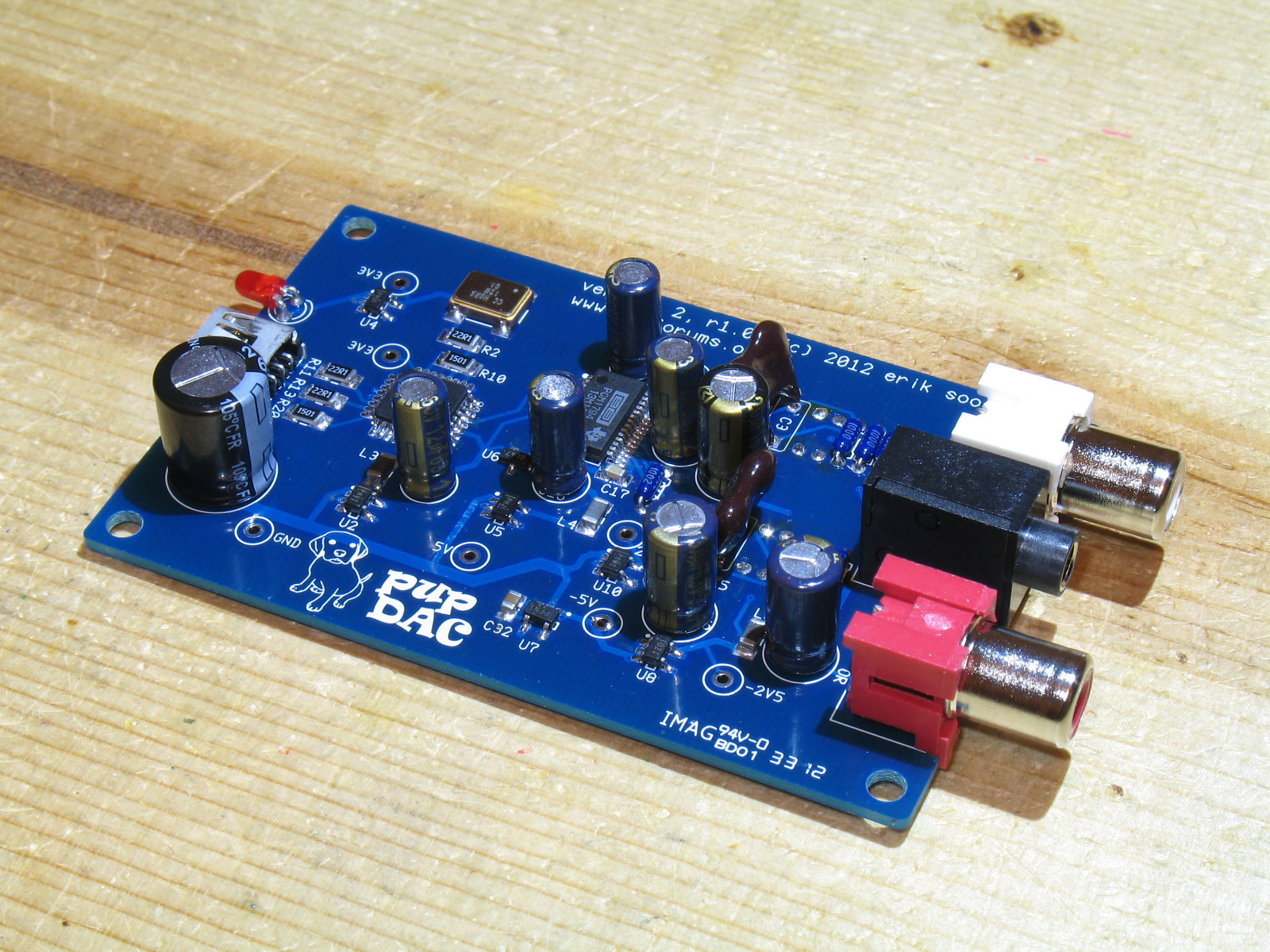
As always, ensure that the rating is visible from the top when you install them. Precision resistors such as these are not color-coded. Therefore, if you don't ensure that the rating is on top and visible, you'll have a hard time confirming the proper values if you need to troubleshoot. (DMM resistance measurements are often inconclusive on a populated PCB - the resistors are often in parallel with other resistors or devices, making it difficult to get a one-to-one reading on the resistor's value.) Warning! Ensure that you pull the leads all the way through and get these resistors as flush as possible. The pupDAC PCB will be placed in the lowest slot of the Beezar/Hammond custom case. There is less than 2mm clearance between the bottom surface of the PCB and the inside-bottom of the case! You will also need to trim all the leads from the bottom of the PCB to guard against shorting. More about that later when we finish the through-hole parts. Trim the leads and continue on with the resistors on the top side: Next up is the LED. Since we're building this for the custom Beezar/Hammond case, we need to know how to install the LED so that it lines up with the machined hole in the endplate. Note that the "Cathode" lead of the LED is marked on the PCB silkscreen instead of the usual "+" or LONG lead. The "Cathode" is the "-" lead or the SHORT one. So to repeat and be certain: The SHORT lead goes into the "C" hole. Here you can see more clearly exactly where to make the bend. If for some reason, you end up with an LED that doesn't have leads shaped like this, then just be certain that you bend the leads so that the flange is flush to the PCB and at the edge of the board: Another view to make sure: Next up in the lowest-to-tallest part hierarchy is the mini-USB jack: Another view showing the "structural" solder wicking to the top side: Next are the Mica capacitors, C3 and C18: Here's another view illustrating how the caps are pulled through so that no bare leads are showing. You may even slightly crack some of the epoxy coating on the high-part of the leads, but that's OK as long as you don't damage the capacitor's main body overall. Time to install the electrolytic capacitors! It's a judgment call as to which is taller - the electrolytic capacitors or the RCA jacks. The drawings will tell you that the RCA jacks are a tad shorter, but I haven't found that to be the case in real practice. I think when you get electrolytics of this size, the variance in the rubber plug exposed at the bottom of the cap is fairly high. Regardless, it's quite easy to hang the PCB over the building board so that you can get the RCA jacks flush to the PCB later on. My method in installing electrolytic capacitors is to place them all in the holes on the PCB. Take my pine piece building board, turn it over and hold it on top of the capacitors while holding the PCB in my other hand. Then while holding PCB on bottom and pine board on top with both hands, I turn over the entire assembly so that the pine board is back on the bottom and the bottom of the PCB with the capacitor leads are on top - ready for soldering. While pressing down on the bottom of the PCB to get the upside-down capacitors flush, I solder one lead each on each capacitor. When that's done for all the capacitors, I flip the PCB over and check the caps for alignment and square them. Them I flip the PCB back over and solder the remaining leads. C2, C9, C16, C19, C10, C26, and C27 are close enough in height to be soldered at the same time using the procedure described above. C22 is just enough taller that you should probably solder that one in after all the others. As mentioned before, the Mica caps (as packaged in the Beezar/Mouser kit packaging) are too big to allow enough clearance for C10. I simply bend the Mica caps like "wings" to either side of C19 as show below: Another view of the electrolytic capacitors installed and the Mica caps bent to either side of C10: The RCA jacks are straight forward. Install them before the 3.5mm/1/8" stereo jack. (The 1/8" stereo mini-jack is the tallest part on the pupDAC.). Note that the solder joints for these are also structural in nature. However, they have real, bent-spring snap tabs at the ground connections, so the pad holes are actually too big to fill-in completely with solder. You will end up melting all the plastic housing if you attempt to do that. Instead, ensure that there's ample solder around the tab and fill-in completely the signal connection pads (the ones in back), so that they proved some structural support. Note that the plastic tabs on the bottom in the front fit over the thin cutouts at the edge of the PCB. This helps to lock them into proper position and ensures that the jacks are flush against the PCB at the top surface and front edge. FINISHED!! Another view of our completed pupDAC: Prior to final clean and rinsing, be certain to trim all the leads underneath the PCB. This includes the leads/tabs for all the output jacks. As mentioned previously, there is less than 2mm clearance between the bottom surface of the PCB and the inside surface of the bottom of the case. Clean and rinse as with a normal PCB at this point. I like to use a toothbrush with the same Walmart 91% ispropyl alcohol used before. Get the bottom of the PCB completely wet with the alchohol, using the toothbrush to scrub around the joints where the flux may be particularly thick and hard. Pat it up with a good paper towel. It may take you 4-6 rinses like this to get most of the flux off. Your PCB should be very shiny and with very little dried, white flux around the solder joints. Be sure you use a clean paper towel each time, or the alcohol will simply re-dissolve the flux in the paper towel. After you've done this, inevitably you've had flux bleed through the test point holes back to the top surface of the PCB. Plus, you have those four resistors underneath whose leads and solder (therefore, flux) are on the top side of the PCB. Use a toothbrush where it will fit, but I find several q-tips work well. You can use them both to apply the alcohol and to dry it up. This works fairly well, because the iamount of flux on the top side should be fairly small. Once you have the PCB clean, rinsed and all the leads neatly trimmed, let it dry for an hour or two (remember that new hygroscopic chip material). After that, installing into the case is a snap! |


file last changed:Wednesday, November 21, 2012 6:00:00 AM Please contact the pupDAC webmaster for questions about these web pages.  |