Buy Boards & Parts:
www.beezar.com
www.beezar.com

The Millett Hybrid MOSFET-MAXed
Setup and Bias Settings
| |||
 |
Power Supply Voltage is a snap to set - simply turn the trimmer screw for the voltage desired
Note that 29VDC is about maximum for most 24VAC walwarts under load. The typical Millett MOSFET-MAX is
set for 27VDC.
Tube Bias is also a snap to set, but slightly more difficult until the tubes are broken in. You should always set bias voltage on the tubes at one-half of the supply voltage. So, for 27VDC supply voltage, you should bias the tubes at 13.5V each. For new tubes, bias may continue to change for several hours. Broken-in tubes will probably reach constant bias voltage in one half-hour or less. |
||
| DB Bias is a little trickier - caution is advised.
It is possible to burn up the transistors before you ever finish biasing the tubes if the trimmers are wide open.
Before applying power to the amp for the first time, screw the trimmers down to their minimums. This is usually
20-25 turns. Either count 20 turns or listen for a click, if your trimmer clicks. Apply power to the amp,
and quickly spot-check the DB bias voltages. They should be less than 50mV or thereabouts. If the bias
voltage is much higher, turn the amp off until you figure out whether the trimmers are operating correctly.
Once you confirm that the bias voltage is safe, then proceed with setting up the power supply voltage and
tube bias settings, first. | |||
| |||
|
Begin setting the DB bias by adjusting the trimmer until you start reading voltage. Unlike BJT's, MOSFETs turn on like a switch. So, there may very well be little to no voltage reading starting out. MOSFET Bias may seem a bit scarier than the BJT buffer version, because of the very high bias currents. However, the sound quality of the amp noticeably improves at the higher biases and the MOSFETs tolerate high heat well. While you can burn them up if not adjusted properly, they are not subjected to the same tendencies toward thermal runaway as with BJT's. In any even, try to work up to about 176mV (80ma) and bias with quarter turns from that point until you reach your target. Remember to wait a while between adjustments to make sure the heat has "sinked" in. |
|||
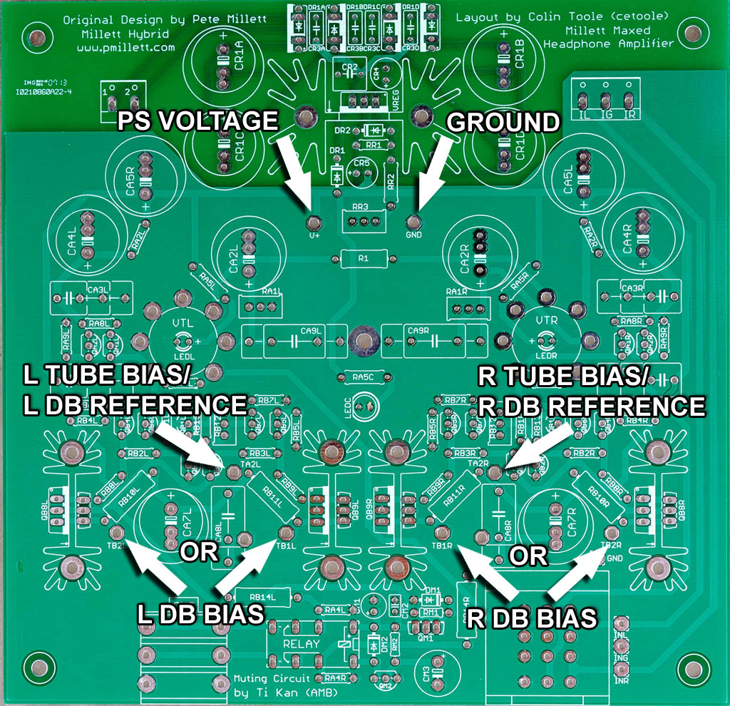
| Power Supply Voltage | |
| Measurement Points: | V+ to GND |
| Adjustment Device: | RR3 |
| Acceptable Values: | 24VDC - 30VDC |
| Tube Bias | |
| Measurement Points: | TA2L to GND, TA2R to GND |
| Adjustment Device: | RA1L, RA1R |
| Acceptable Values: | 1/2 of Power Supply Voltage |
| MOSFET Bias | |
| Measurement Points: | TB1L or TB2L with TA2L, TB1R or TB2R with TA2R |
| Adjustment Device: | RB12L, RB12R |
| Acceptable Values: | 220mV - 275mV (100ma - 125ma) |