Buy Boards & Parts:
www.beezar.com
www.beezar.com

The Millett Hybrid MOSFET-MAXed - Tweaks
Millett MOSFET-MAX Tube Lights
One of the neat things that's always attracted people to the Millett are the look of the tubes and
the lighting that they create. Unfortunately, the dirty little secret is that contrary to popular
opinion, most low-voltage tubes do not produce even minimal light on their own. Instead, the traditional practice
with the Millett and other tube amps has been to provide supplemental lighting with LEDs. Good tube
lighting can enhance the listening experience. The liquid sound imparted by the tubes is psychologically
reinforced by lighting - making the tubes almost appear as if they're filled with lighted fluid ...

|
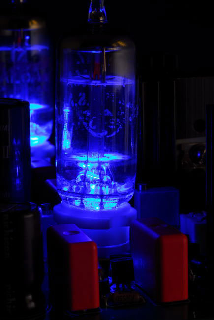
photo by Neil Rothschild
|
| ... or you could just say they look cool!! | |
|
LED's
The Millett MOSFET-MAX provides pads on the board for T1-size (3mm) LED's under the tubes. Inexpensive, but very
bright LED's are also specified in the MOSFET-MAX BOM.
| |
|
You have two choices for mounting the LEDs: 1. Mount the LED flush with the board as shown in the photo at right. The high-brightness LED's are very directional, and while some light escapes from around the tube socket legs, there is more than sufficient light directed up into the tubes. This is probably the default choice for most builders. 2. Mount the LED into the socket. This is accomplished by pushing the LED up into the center hole of the socket from the bottom. Hold it in place with a small strip of tape between the LED leads. Once soldered into place along with the socket legs, it will not move. |

|
 |
Socket Take-Apart Methods
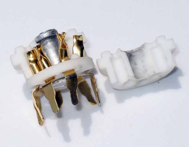
Of course, for best effect, there must be an open center hole in the socket. Unfortunately, the favored
ceramic type PCB sockets do not come with open center holes. There is a soft metal two-part pin in
the center holding together the two halves of the socket. This wasn't intentional, but the photo shows
a cutaway of the typical ceramic socket construction - two halves held together with a two-piece pin
in the center. The socket pins are held in place by the base, and slip into holes in the upper half
of the socket. This allows the pins to be forced open by plugging in a tube.
|
| The most dependable method is to carefully drill the pin out. This isn't as bad as it sounds. A 3/32" drill bit actually works better than a larger one. The idea is to drill through the top pin. Once the bit penetrates the hollow top pin, the bit can simply push the bottom pin so that it falls out from the bottom. A good method is to clamp the socket between a couple of pieces of wood, so that the top lip of the socket overlaps the wood. |
 |
|
This way, you don't have to clamp too hard - the lip holds the socket from falling through.
Careful with the pressure, though - these pins sometimes might as well be glued or welded together.
I've also had the soft metal literally melt into the drill bit grooves. So, a little bit of cutting
oil is warranted to keep things cool. Don't press too hard, or the result will be the broken socket
pictured above. Once you get them separated, remove the pin and glue the two halves back together
(without the pin, there is nothing to hold the halves together unless you glue them). 5-minute epoxy
will work, but 15-min is better if you can find it. Most hobby shops will have this epoxy and
some hardware stores. CA (Cyano-Acrylate superglue) glue will work as well, but the thick or gel type
is best. The glue must have gap-filling properties to be useful. DO NOT use the newer "Gorilla Glue"
polyurethane type glues. These will expand into the pins while curing and render the socket useless.
| |

photos by DIYForums user "James281" |
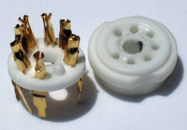
Some have had luck wedging a small flat screwdriver tip into the key slot that existing between halves.
A very careful touch may be able to slightly twist the screwdriver tip so that the socket halves put
enough opening pressure on the pins that they come apart. An example, before and after, is shown at
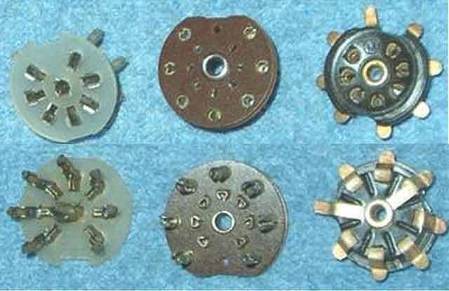
left. One reason this may not work is because of the variance in socket construction. There are two
styles of the 7-pin ceramics. One style has somewhat equal-thickness ceramic socket halves. The other
has a very thin bottom piece. The take-apart photos shown earlier are of the thin-bottom type, which
may be very difficult to pry apart using this method - the thin bottom cannot withstand much stress before
breaking. The photo below highlights these differences. Drilling is recommended with the thin-bottom
type. |
|
Types of 7-pin PCB Sockets
 |
There are gold, 7-pin PCB sockets available from beezar.com. Parts Connexion also sells gold-plated PCB 7-pin sockets.. Gold-plated chassis-mount 7-pin sockets are available from several sources, but not PCB ones. |
|
The regular tin-plated sockets are available from several vendors such as TubeDepot and theTubeStore,
and in quantity selections of 7 or 10 from an e-bay seller at present. In addition, there are a number
of different socket style alternatives to the ceramic, several of which are suitable for PCB mounting:
Due to the high-bias currents required and the potential resulting heat, ceramic sockets are recommended for the MOSFET-MAX.
If you experiment with others, be sure to check how they may fit into the PCB pads. You may need to whittle down the mounting legs. Chassis-mount ceramics may work by doing this, too, but it may be a risk to deviate. |
|