www.beezar.com

|
|

|
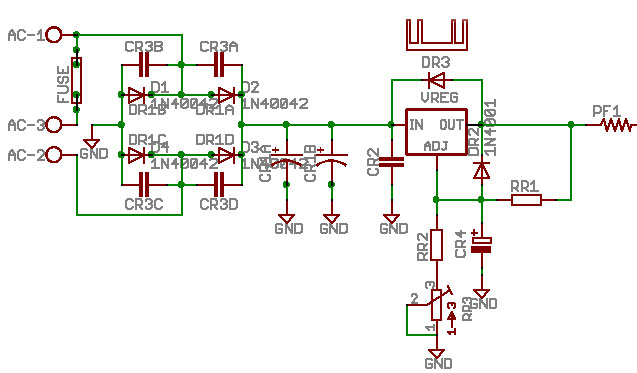
The power supply schematic for the MAX V1.2 PCB is based on the LM317,
TO-220 voltage regulator. The power supply is essentially the same power supply developed for the MiniMAX. Extensive testing went into the MiniMAX PS to obtain the lowest noise possible. Using the recomended configuration shown here and on the BOM and just as with the MiniMAX, the MOSFET-MAX power supply is capable of providing clean, linear-regulation with noise down below 0.040mVAC. Besides the basic LM317 voltage regulator circuit (shown in Figure 1 at left), Schottky rectifiers with ceramic snubber caps and 2 x 1000uf of filter capacitance round out the additional features. Also included is a buss fuse (5x20mm) at the input terminal block for walwart protection. |
| Some Class II walwarts do NOT have overcurrent protection that can be reset. The MOSFET-MAX buss fuse can protect those walwarts by blowing first. Most important is a current limiting Polyfuse, "PF1", used to connect the power supply to the rest of the MOSFET-MAX circuit. Note that for the MOSFET-MAX, we've upped the rating on the Polyfuse to 0.75A (the MiniMAX uses 0.5A). The Polyfuse serves two purposes: 1) It provides just the right amount of resistance to optimize the low noise characteristics and 2) it provides over-current protection for the buffers. Of course, as with other MAXes, the power for the MOSFET-MAX is supplied with a simple Class II, 24VAC walwart. | |
|
The standard MOSFET-MAX buffer bias is recommended at 100-125ma. A 1000ma minimum, 24VAC walwart will provide plenty of current and have enough reserve to prevent transformer saturation. Referring to the LM317 diagram above, "Figure 1," the governing equation solves for the output voltage capability for the voltage regulating circuit. The LM317 operates by maintaining 1.25V for Vref. In the MOSFET-MAX, "R2" in the diagram is actually the 1K trimmer - RR3, plus the 2K ohm resistor - RR2. The MOSFET-MAX uses 120 ohms for the "R1" resistor (RR1 on the MOSFET-MAX BOM). Assuming the highest and lower adjustment for the 1K trimmer and solving the equation for both cases, the MOSFET-MAX power supply gives a voltage adjustment range of 22.1VDC to 32.5VDC. Note, however, that if the line voltage deviates significantly from the 120VAC standard in the US, this range may be less. | |
| However, we recommend that you only use this range of adjustment to ensure 27VDC as measured at "V+" and "GND" on your MOSFET-MAX. | |
Much of the history of the MAX PCB V1.2 power supply design development is detailed on the MiniMAX history page. Several things were found in our extensive testing to minimize noise and ripple from the MiniMAX power supply:
| |
|
As you can tell from reading the Power Supply testing history, there is a complex combination of settings and part selection that results in the very low noise the MOSFET-MAX team has achieved. Not the least of those is that the LM317 is rated for maximum ripple rejection at a 5V drop. This is the approximate value that results from the specified walwart - after rectification and regulation down to 27VDC. Consequently, we recommend the 27VDC setting for best results. | |
|
|