Buy Boards and Parts:
www.beezar.com
www.beezar.com
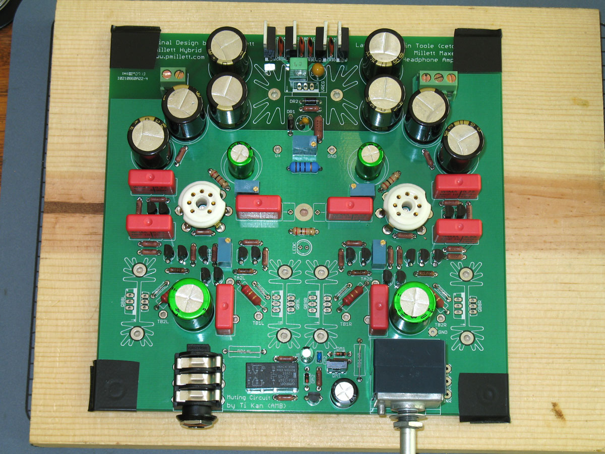
The Millett Hybrid MAXed - Construction
PCB Construction
Preparation -
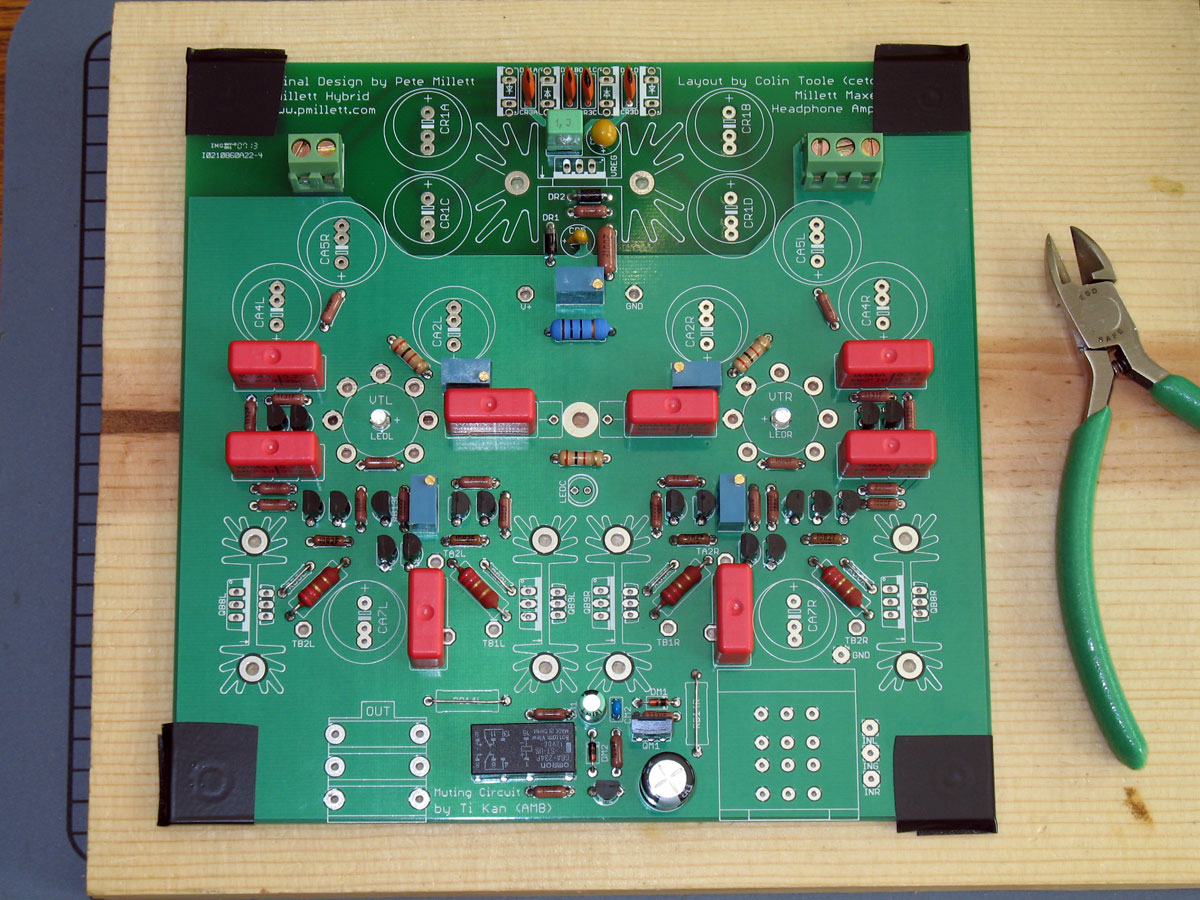
Start the Millet Max as you would any electronics project. Gather your tools,
print out a nice copy of the layout, schematic, and bill of materials. Some of the tools you might need are
shown: smooth-jaw needle nose pliers, flush cutters, scissors to easily open parts bags and cut heat shrink,
and wire strippers. A helping hands is pictured, although it has limited effectiveness in the case of the
Max - the board is so big. You might try two helping hands, and suspend the board
between them. I've tried that, but truthfully, a good flat board is just as handy in this case (explained below).
|
 |
|
The lead bending jig is a nice touch. Although you will find that most resistor leads should be bent as close
as possible to the resistor body for the Max's pad layout.
|
|
|
NOTE: You must decide which type of Diamond Buffer output stage to use - either BJTs or MOSFETs . You cannot build both, and the parts in the next sections depend on that decision: BJTs or MOSFETs. (construction shown is for BJTs)
|
|
 |
Matching Transistors -
A good place to start the Max is to match the transistors. In the case of the Max,
this means the 2N5087 and 2N5088 transistors. Matching the JFETs and BJT output transistors has limited usefulness.
Matching the MOSFETs if you use that option is a good idea, but Team Millett Max recommends purchasing
the MOSFETs from Amb, and the matching service is included in that case.
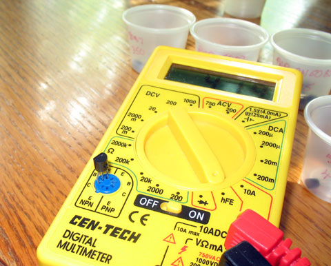
The previously mentioned $2.99 DMM is more than adequate for measuring HFE of the transistors. As seen in the photo, |
|
I usually line up a bunch of cheap, tiny measuring cups and label the HFE value on the cups. In most cases, each cup accepts
a range of about 5. I end up with one line each of about 6-10 cups, depending on how wide the transistors range. If there's
a bunch that are more than 10 away from a certain cup, I label a new cup. My latest buys have been ranging from HFE's of about
300 to 550. You'll probably find one transistor type ranges from 300-400, and the other type from 400-550, or something like
that. Chances are you won't get many that are the same from 2N5087 to 2N5088. Instead, try to get them equally matched among
type. For instance, I found a bunch around 375 for one type, and a bunch at around 425 for the other type.
Make your selection at one value for each, and hopefully from cups that end up with about twice as many transistors as you need. The reason? Once you've made your selections, check each one again before you solder them into the board. You'll find perhaps 1/3 to 1/2 are not so close anymore. This method has worked well for me to keep a pretty even match between output channels. Hint: Rigorously check for close HFE tolerances on the Constant Current Supply to the tubes (2 - 2N5087's per tube). |
|
 |
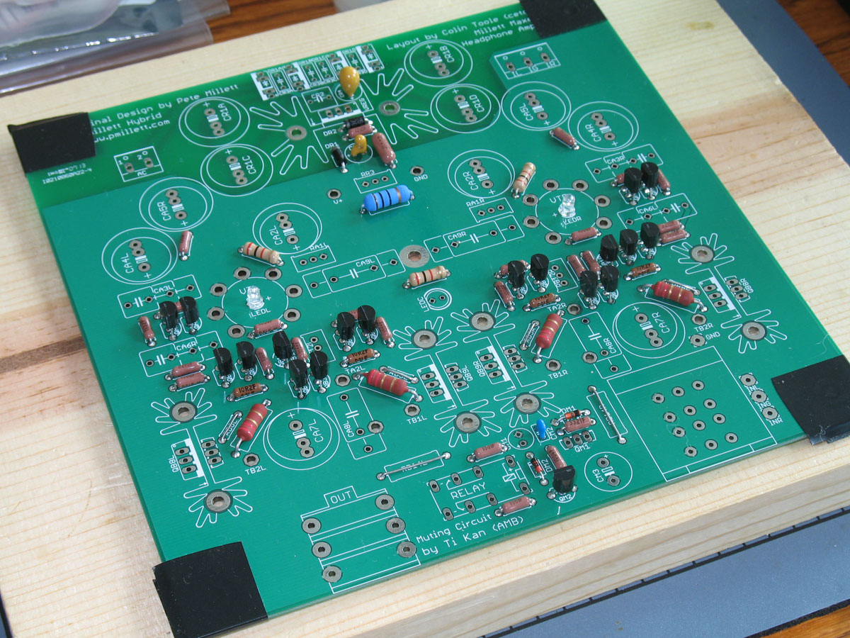
Populate the Resistors -
Begin populating the board with the smallest parts. In order of the parts selection on the BOM, these are:
1. 1/8W V-D resistors
2. 1/4W carbon/cheap LED resistors
3. output power resistors
4. tube heater resistor (R1)
As noted, the board is really too big for a Helping Hands. Two works OK, but it gets pretty inconvenient flipping
the board to check the parts. HINT: Apply electrical tape on the corners of the board. This prevents the Helping
Hands alligator clips from scrathing the board and exposing the ground plane. I had good luck, though, with mashing down flay on the board against the building board.
The standard technique is to solder one lead, while holding the iron and keeping the solder melted, gently mash down
so that the part is pushed flush against the top surface of the board from below. The second lead is then a snap
to solder in place, and your part is nice and flush against the board. After soldering/mashing that first lead,
flip the board to check that the part is flush and in position, then flip it over again and solder the second lead.
Check as you go along for other parts in the Power Supply or the e12 circuit that may be at similar heights to the resistors.
When you've populated every part you can of a lower height, the small transistors and JFETs are next.
|
Populate the Transistors -
When not carefully
soldered, TO-92 transistors can look like a bunch of mold spores popping out in every direction. There are a couple
of things you can try to keep this from happening. Push the transistors down into the holes as far as they can go. Be
careful, because you can break a lead out of the plastic body - ruining the transistor. In any event, pushing the
transistor down as far as it will go (within reason) puts a little more force on the pins and helps to keep them
straight. With a little practice and luck, you should be able to push all of the smaller transistors into place all at once.
Flipping the board over at that point will let you balance the board on the flat-top surface of the transistors.
As with the resistors, pick a lead to solder on one of the transistors. However, in this case, try to apply even,
consistent pressure over the whole board. This helps to keep all the transistors at the same mounting height. A good
practice to avoid overexposing the transistors to heat is to solder one lead on each transistor. When one lead on each
transistor has been soldered, flip the board over and check for alignment and equal height. Carefully bend any transistor
that is out of position. Flip the board over and solder the second lead of each transistor before soldering the third leads.
This keeps the exposure time down per transistor and treats the transistor much better than if you soldered all three leads on
one transistor before soldering the next one.
|
|
 |
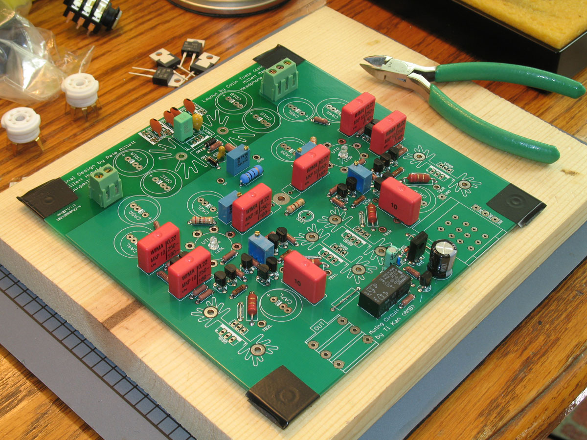
Film Caps, Misc Parts -
Things start going fast as this point, as you add the trimmers, film caps, power supply recitifiers and miscelaneous e12
parts. Check for other parts that are shorter than the tube sockets. This is important, because the tube sockets are another
part where alignment is important. If you install a part taller than the soldered-in tube sockets, you will not be able
to get them pushed down all the way in the holes for proper alignment.
Take care with some of the longer parts - the film caps and the relay. It's easy to get these turned. As before, solder a single lead, flip the board over, check for alignment and bend slightly as needed. The distinct silkscreen on the Millett Max aids in this task. Flip the board back over and solder to finish installation of the part. I've also found some difficulty in soldering the terminal blocks flush to the board. Some of these blocks actually have a portion of the pin twist below the bottom surface of the terminal block, preventing it from soldering flush without pushing down on it with some force. Yours may be fine, though - but check for this just in case. |
|
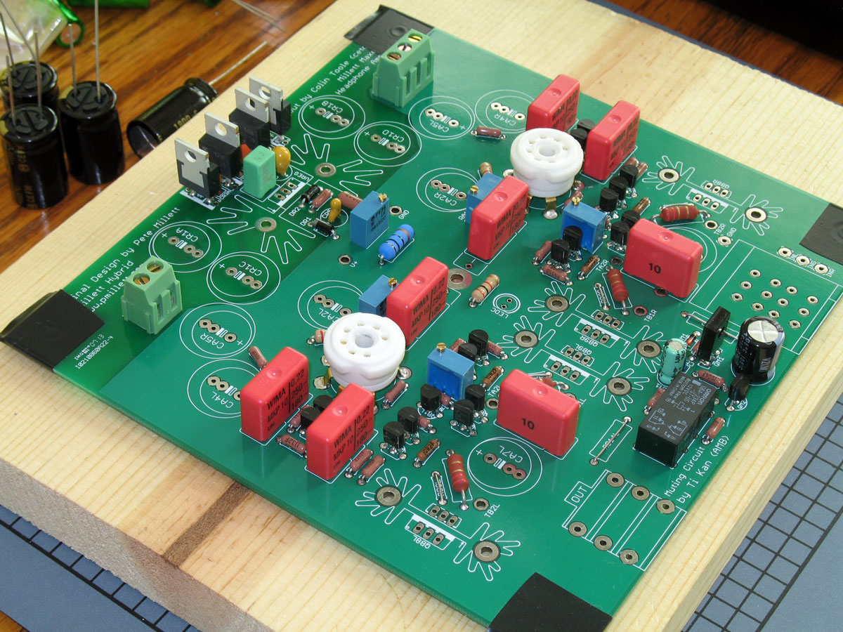
Solder the Tube Sockets -
Once you're sure that you've installed every part that is shorter than the tube sockets, it's time to put those in. Note the
hints about using these with LED's in the Parts List section. All of the ceramic sockets that most of us use for the Millett
have center pins that must be removed in order for the tube LEDs to shine through from below.
Once you've prepared this feature if desired, it's time to solder the sockets in. Take extra care in doing this. Since the tubes seat on the top surface of the sockets, if they are out of alignment, the effect is multiplied many times because of the tube height. So, care in getting them straight pays off. Begin by trying to bend all of the pin tabs in equal amounts. These vary considerably, from splayed out to almost straight. Test the fit of the socket on the board - is the hole centered on the LED, is the top surface of the socket level from side to side and front to back? If not, remove the socket and try bending the tabs more or less on one side of the tube. Repeat as necessary. Once you're certain they are as straight as possible, solder them |
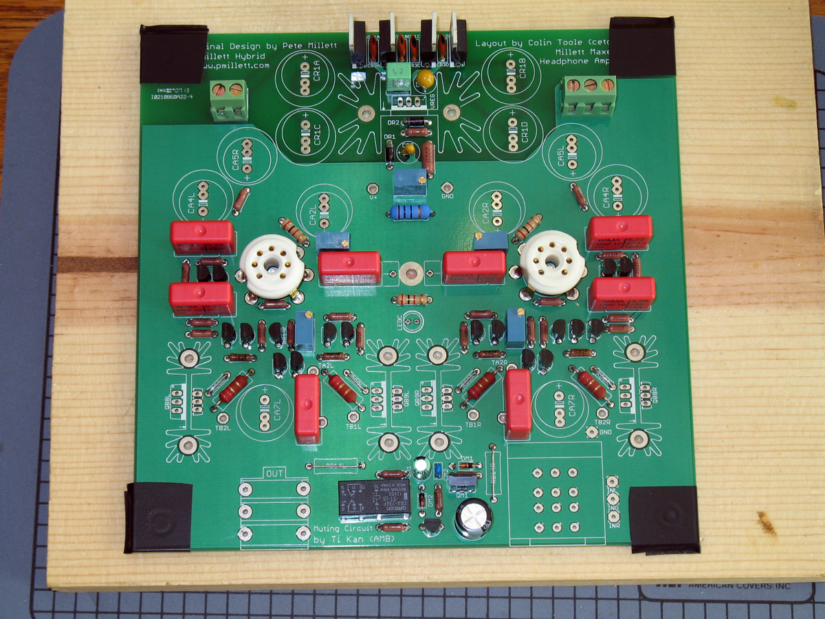
|
into the board. I've found that the transistor method outlined
above works well. Put both sockets in at once, flip the board over, and "tack" solder one pin on each, while pressing down vertically
on the board to get them well-seated. Flip the board over and re-check for proper alignment. If OK, then solder the remaining
pins. I flow the solder into the holes in copious amounts, so that the pin holes are completely filled. The sockets
undergo considerable stress when plugging and unplugging tubes.
|
|
 |
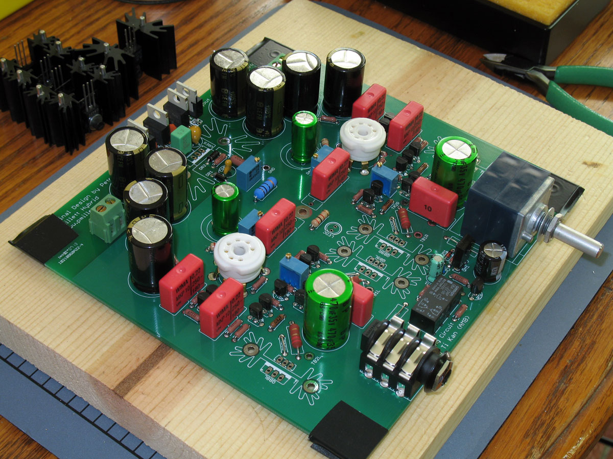
Large Electrolytics -
Similarly, add the large electrolytics by bending the leads enough to keep them from falling out. Flip the board over and press
down while soldering one lead. Flip the board over and check for final alignment, and solder the remaining leads. As with the
transistors, it's almost easier to put them in and solder them all at once, since several of them pretty much support the board
when upside down.
Depending on which pot you've purchased, this would be good time to install that, too. |
 |
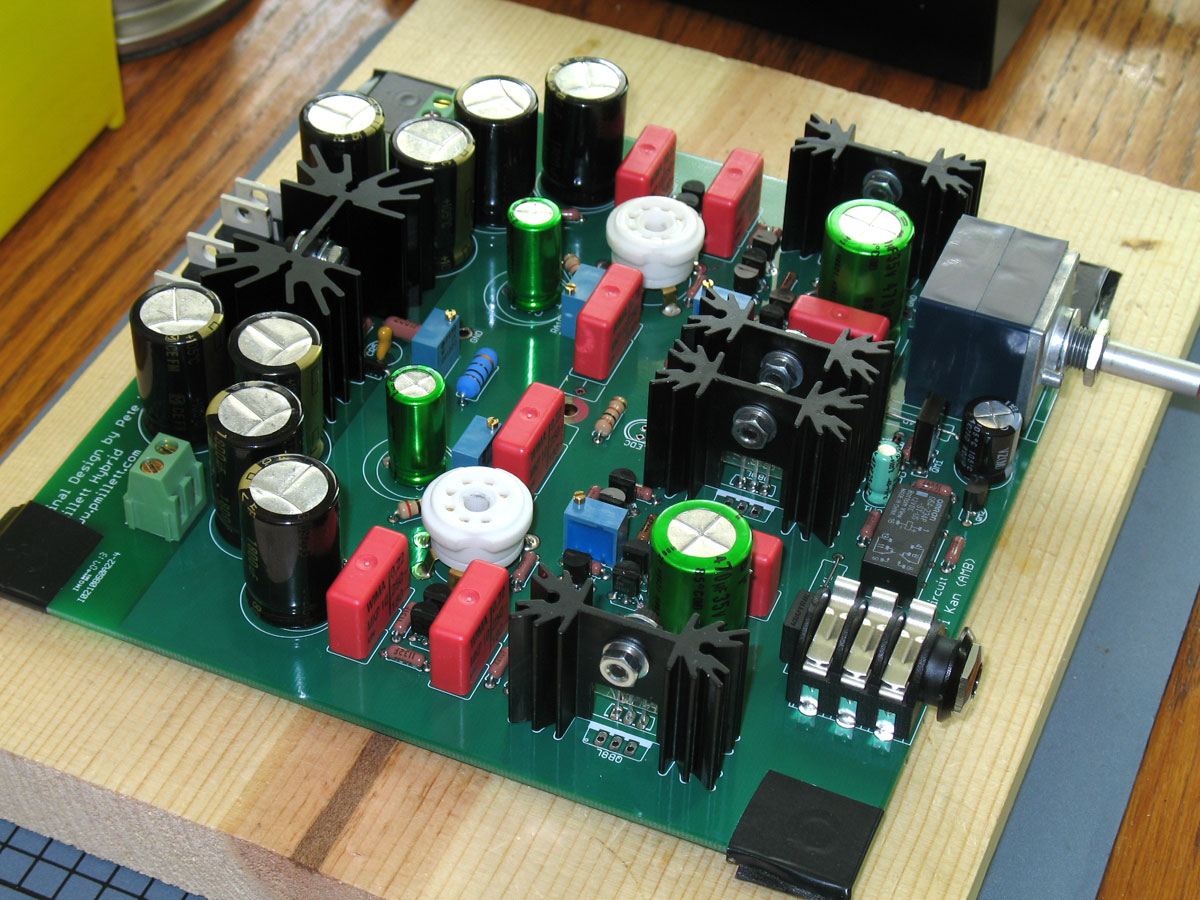
Solder the Heat Sinks and Output Transistors (or MOSFETs) -
Time for the heat sinks, output transistors, and the voltage regulator. You can make these assemblies up anytime. I like to assemble
them completely except for leaving the screw and nut slightly loose. This relieves any stress that may occur from small misalignments
when you solder them into the board. You should always use goo - no surface is smooth enough to give perfect heat transfer. The goo
helps to fill in those unseen spaces without losing much in heat transfer effectiveness. Properly applied and with the screws tightened
down, |
| effectiveness is much better than without. I also use the Mica insulator, but that's more of a personal opinion. If you ever
have the possibility of the case touching the heat sinks, then this is a prudent measure. My method is to appy goo to the back of the
transistor/regulator, then to one side of the mica insulator. The mica insulator will "stick" to the transistor and stay in position
while you insert the screw, washers, and nut. You should use an insulating shoulder washer on the regulator, but it will not fit on most
of the suggested transistors.
|
|
 |
As with the predominately suggested method, flipping the board over and pressing down slightly while soldering is a no-brainer in the case of the heat sinks. Their top surface provides a huge support surface for the entire board, and makes soldering them flush a snap. As always, though, tack-solder on one side, flip the board and check for alignment. Then flip the board back and finishe soldering the sinks and the transistors. You may have to turn up the temperature when soldering the pins on the sinks to the board. Lower temperatures just get sucked into the heat sink, preventing sufficient temperatures from developing at the pins to melt the solder. |
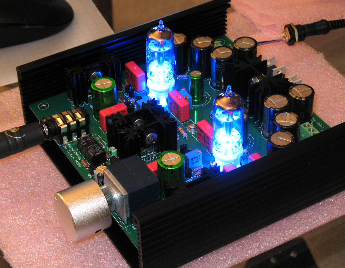 |
Here is the finished Millett MAX, or at least until I get around to drilling the endplates. |
