Buy Kits & Parts:
www.beezar.com
www.beezar.com

The ECP Audio
T
O R P E D O
| III |
differential hybrid parafeed headphone amplifier
| |
Construction - PCB part 4
Moving right along, we installed C5: C3: 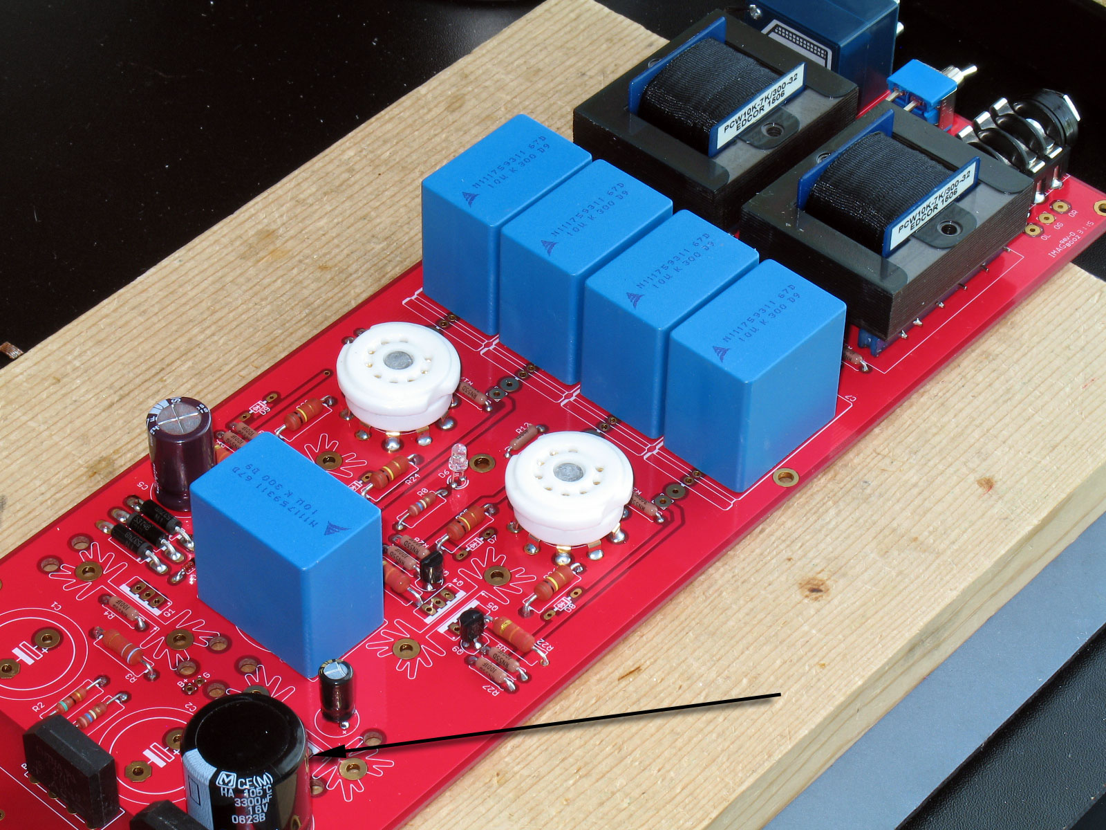 Next up was C6. It has a silkscreen for either a large film box cap (as shown here) or an electrolytic. I asked Dsavitsk which to use and he said the film cap sounds better. Good enough for me. 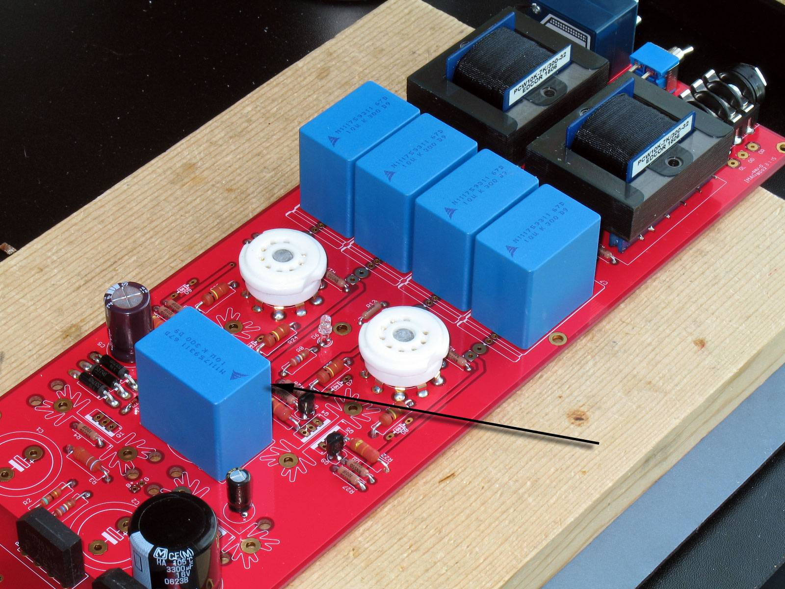 |
In the case of the Torpedo III, Dsavitsk arrived at 10uf for the parafeed capacitors. Needless to say, that's pretty big. The Epcos capacitors shown here are what will be supplied in the kit. They have a great reputation for sound quality at an inexpensive price. So, C7, C8, C9, and C10 were installed: Next up are the heat-sink mounted solid-state devices. Because of the differential part of the circuit, there are two output transistors for each channel (as shown in the circuit schematic above). 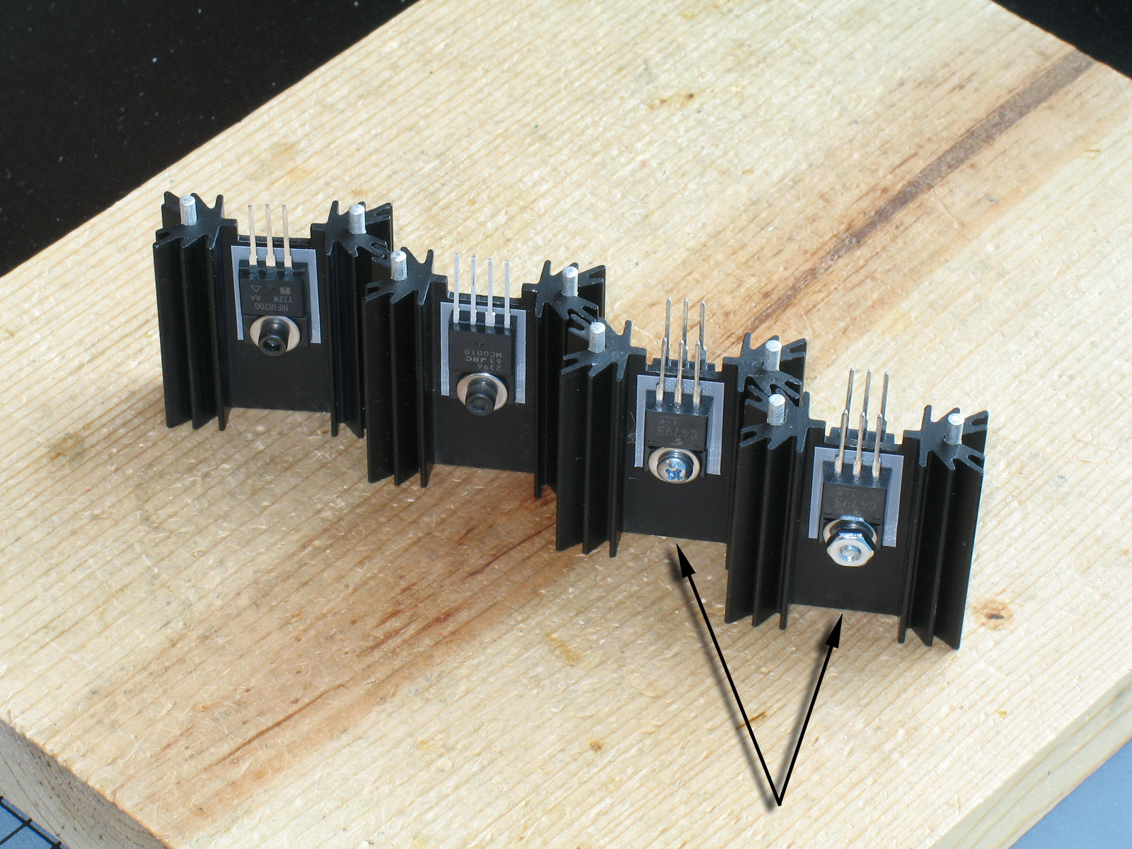 Note the two heat sinks on the right. They have transistors mounted on both sides to handle the four signals coming from the two tubes. Solder all of these into place on the PCB (refer to the silkscreen labels and the BOM for the correct parts): 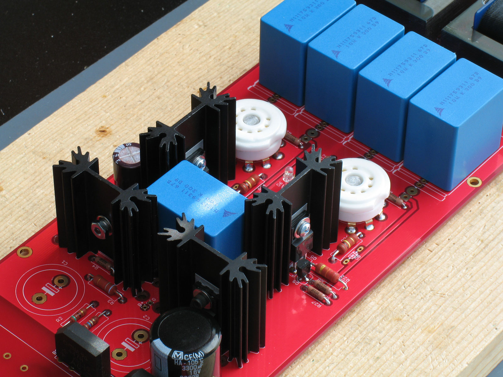 |
The RCA jack comes next - be sure you push the tabs all the way into the holes.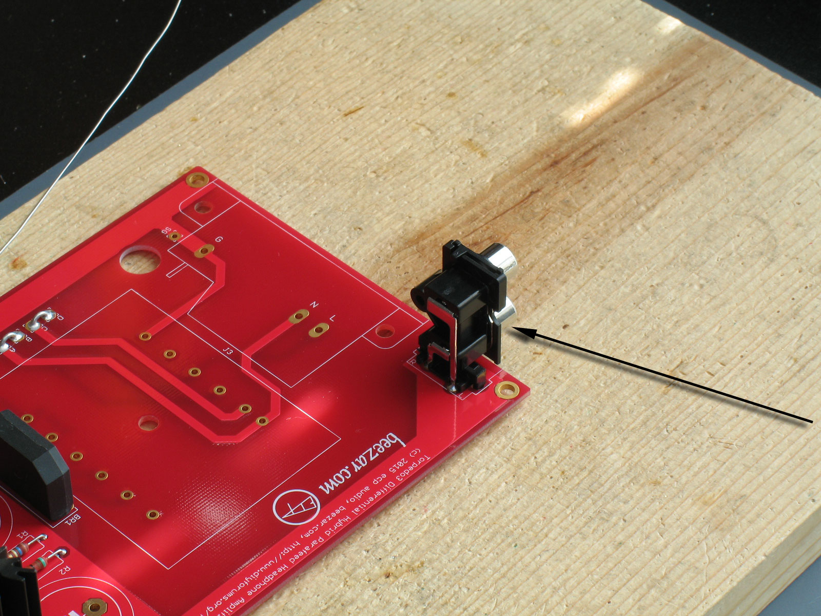 The only capacitors left to install are the two large power caps, C1 and C2:  Next up is the Power Transformer (PT). It might have been the IEC inlet because it's shorter, but that will be explained on the next page.: 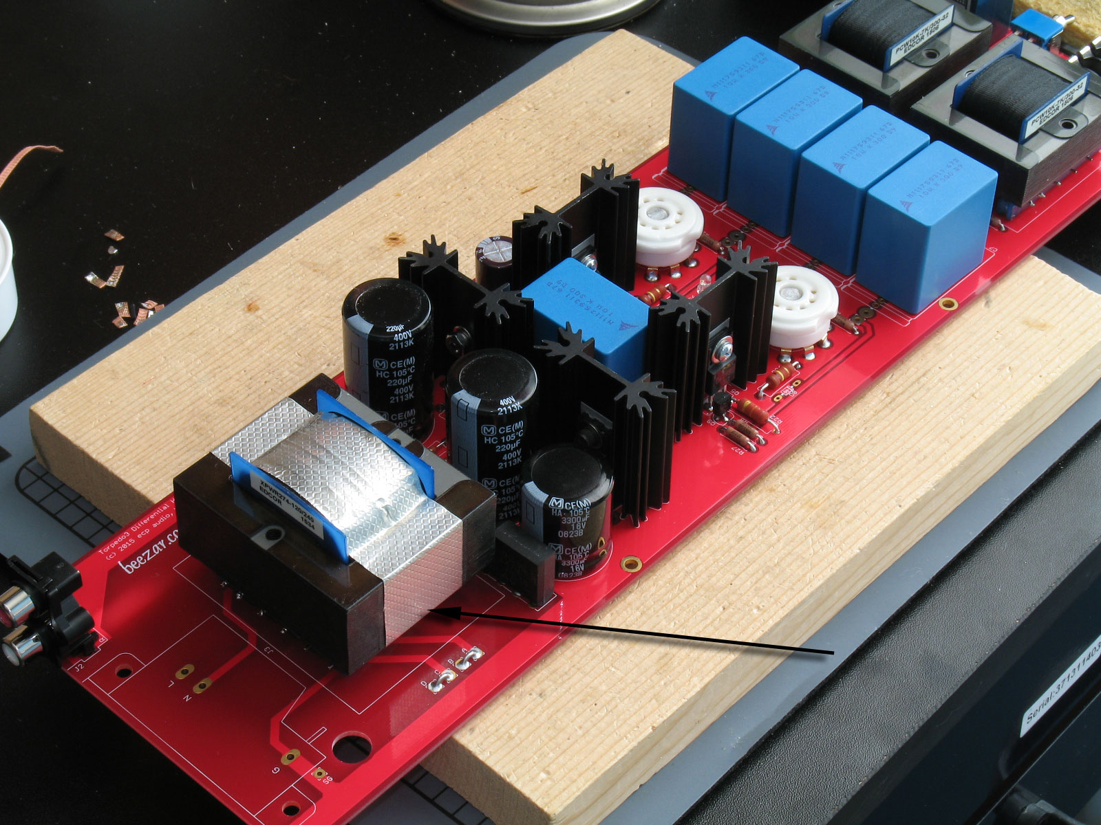 As with the OT's, try to get the PT flush and alternate soldering pins from one side to the other, so that you don't melt the plastic rails. When you turn the PCB upside down, try to stabilize the rest of the PCB. At this point, the PCB is a very long lever arm with big weights on both ends. The PCB will definitely flex, or worse - if you let it. |
file last changed:Saturday, October 31, 2015 6:59:41 AM
Please contact the TORPEDO III webmaster for questions about these web pages.