|
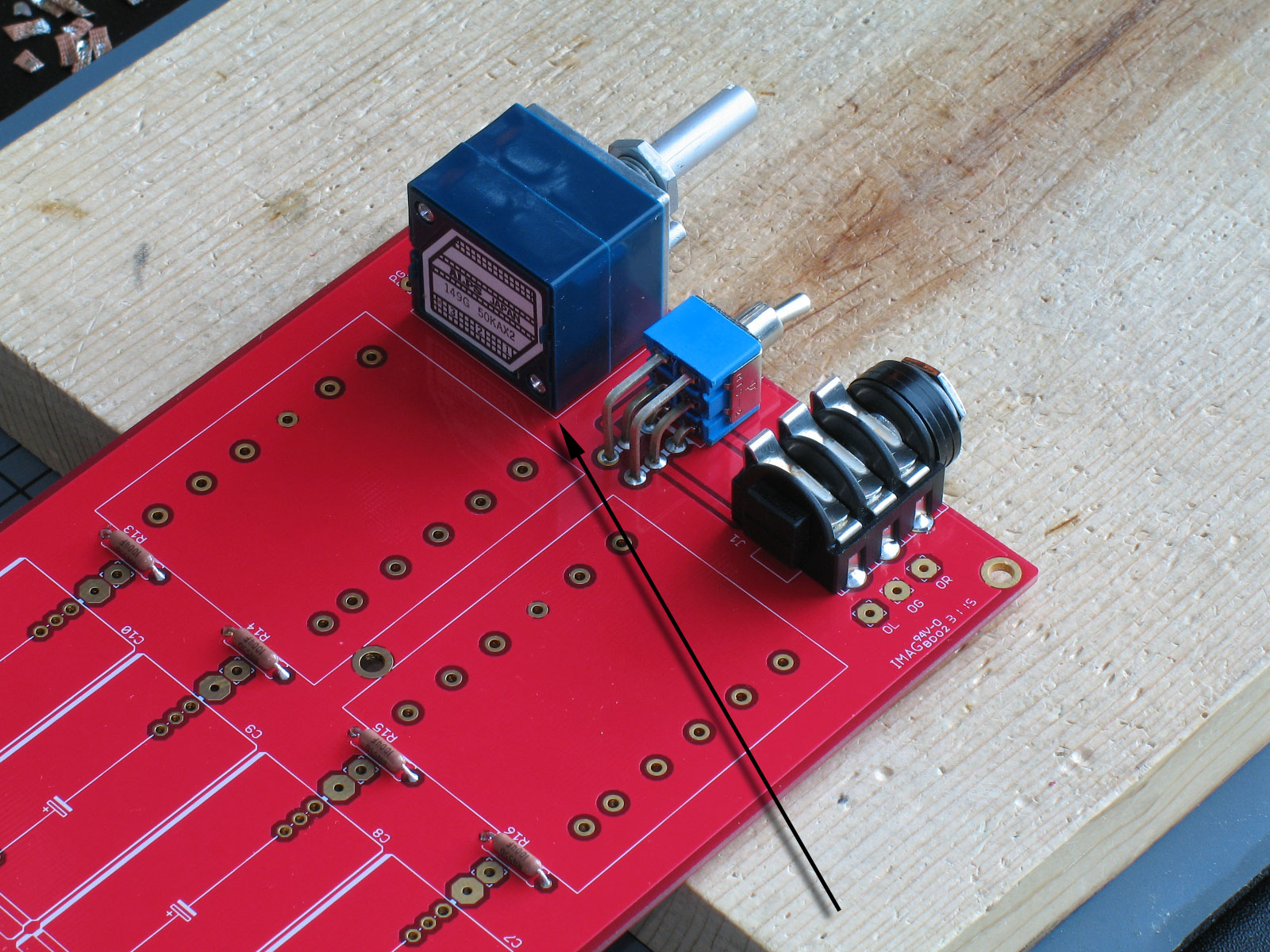
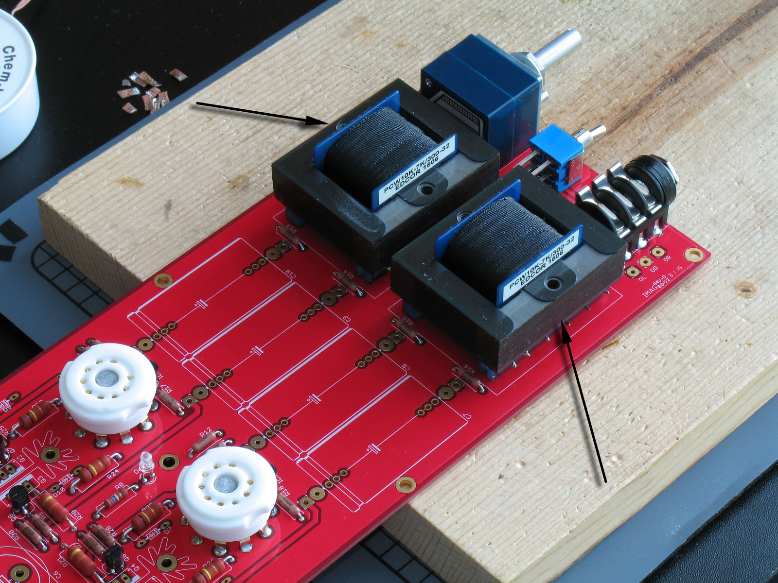
The ALPS Blue Velvet volume pot is next:

As with the headphone jack, remember there's a lot of plastic there, so go slow on soldering the six pins and try to allow sufficient cooling between joints. Also as with the headphone jack, do your best to have the pot shaft parallel to the top surface of the PCB and perpendicular to the front edge of the PCB. This will make aligning the volume knob much easier when you case it up.
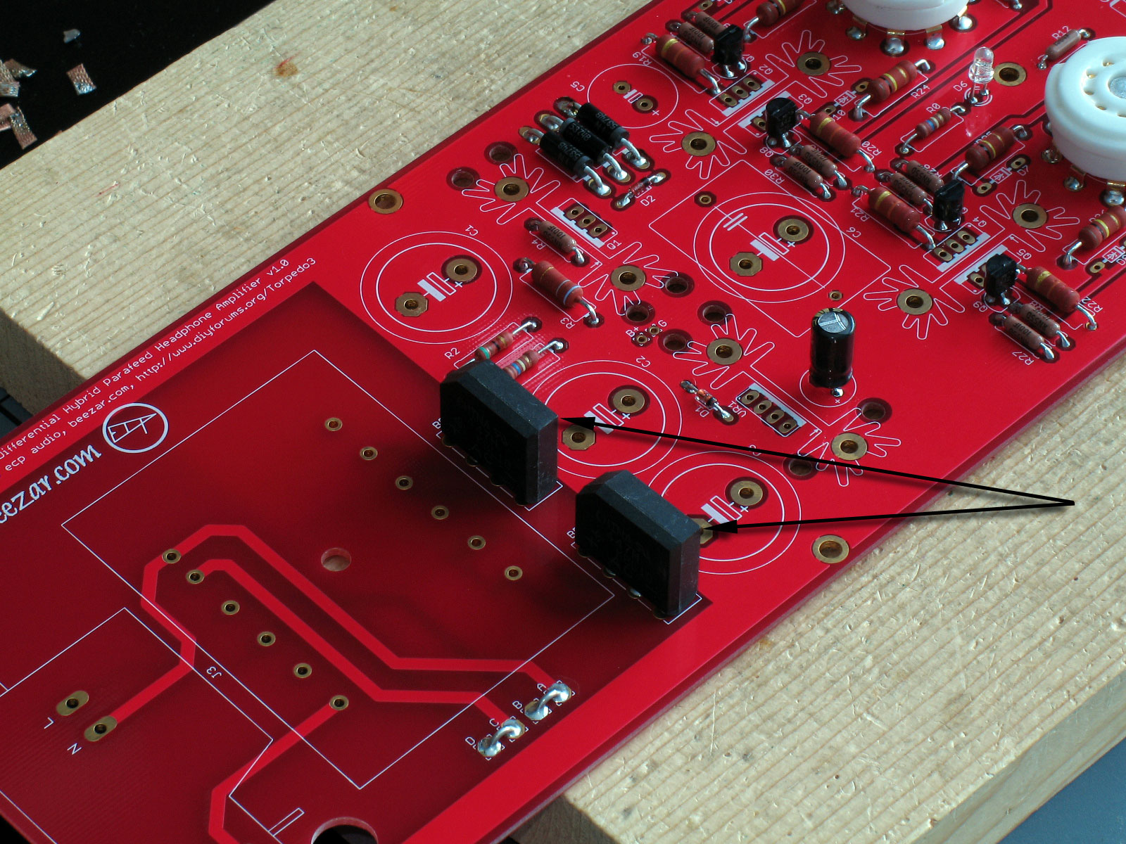
I soldered the output transformers in next:

As with everything else, try to keep these flush to the PCB and oriented orthogonally. Rotate soldering the pins in a sequence to keep things cool. The PCB pin runners on the transformers are plastic and they will melt. Solder a pin on one transformer and then solder the same pin on the other. Go back to the first transformer to solder the next pin, then switch to the other transformer. Do this taking turns from one transformer to the other and you should be able to keep things cool.
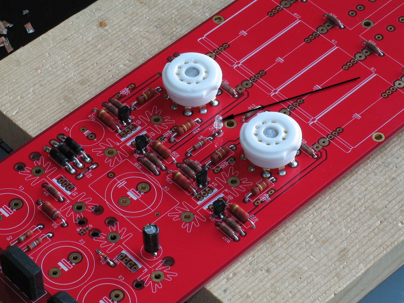
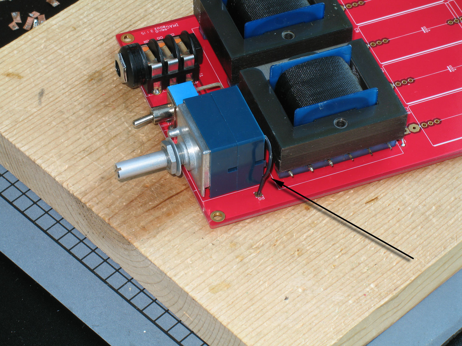
So ... what do I always forget before this step?
The dadgum ground wire for the pot!

It seems I do this every time I build a Torpedo: forgetting to install the ground wire before soldering in the output transformers. Luckily, I have a very small screwdriver that I can use, so I can get the pot screw tightened securely down on the ground wire, even though the OT is in the way. You can probably see a little scrape mark on the laminations in line with the pot screw.
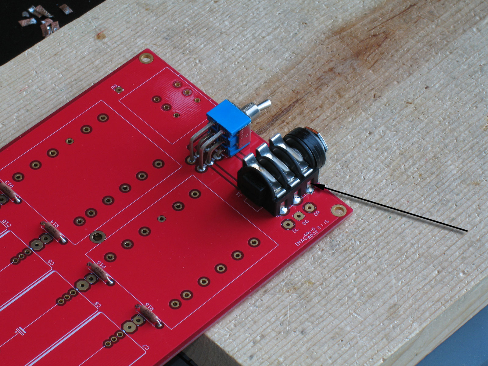
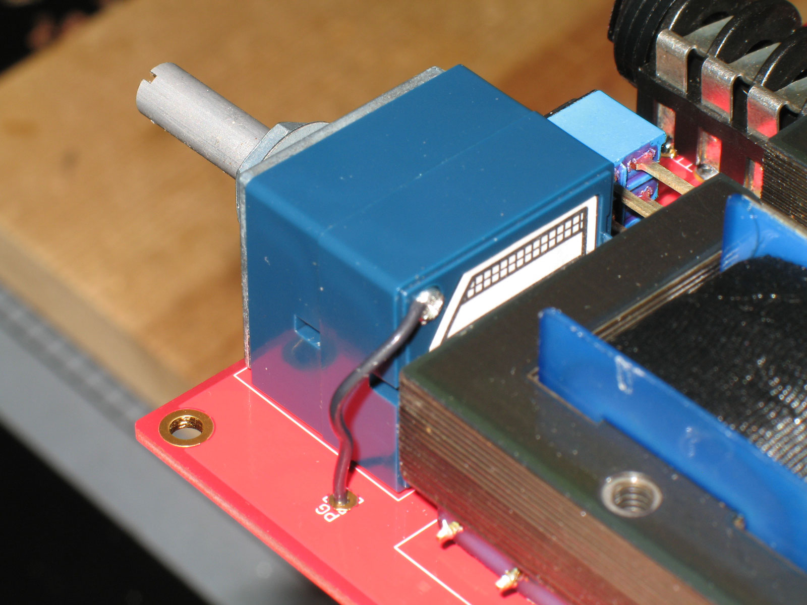
Another view:

It may take some effort, but be certain the screw engages the front panel of the pot and that you have some ability to make it tight. In my case, I always use 22ga SPC teflon hookup wire (Navshipps/John's Wire Shop on ebay). It's pretty thick compared to the screw, though, but with some effort you can get the wire compressed under the screw and actually have it threaded into the pot's front panel.
Needless to say, this is an awful lot easier if you do it before soldering in the OT's.
NOTE: You will not be able to install the volume pot ground wire later if you use and install the Cinemag OT option. The Cinemags are taller than the Edcor OT's and will not give you enough room to reach the pot screw. Install the ground wire prior to installing the OT's. |