www.beezar.com

|
Step 9. - Install the TO-92 transistors, Q1, Q2, Q3, and Q4. Two of these transistors are used in the CCS's, while the other two form part of the unique transistor-based tube bias (full explanation on the Torpedo website). These transistors are familiar to Millett/MiniMAX/MOSFET-MAX builders and are the ubiquitous 2N5087's. At this point, you can install the optional capacitors C7 and C8. I didn't install them and haven't missed them in a previous prototype build. So, my next step is installing the C6 capacitor: Step 10. - Install the C6 capacitor. This is the small electrolytic capacitor that forms part of the circuit for the regulated heater supply: Oops! You can see a mistake I made: installing the C9 and C10 capacitors (those red Wima's). Not a big problem, but the next step should be installing the impedance switch. Step 11. - Install the impedance switch. This is a mechanical/electrical connection, so ensure that the solder joints are properly wicked to the top side of the PCB and that the pads are fully-filled with solder: Note the wicking up along the leads. Also, do not forget to solder the tabs of the front plate of the switch. As with all three components at the front of the PCB (volume pot, headphone jack, impedance switch), take care to line everything up and ensure that the part is flush against the PCB. The reason I use a pine board as my PCB building board is so that I turn the PCB over and apply pressure to the bottom of the PCB while soldering the leads. This ensures that the parts are flush. Oops! Dsavitsk snuck this one in on me - there are jumpers in the signal traces to the pot if you wish to wire in a different pot or attenuator. We're sticking with the venerable Alps Blue Velvet (RK27), so we'll solder in jumpers for these: Step 12. - We'll ignore my mistake in jumping the gun on the Wima's and you should properly solder them in as Step 12: The tube sockets are next in Step 13! |
|
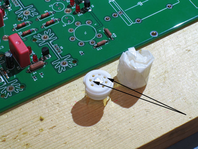
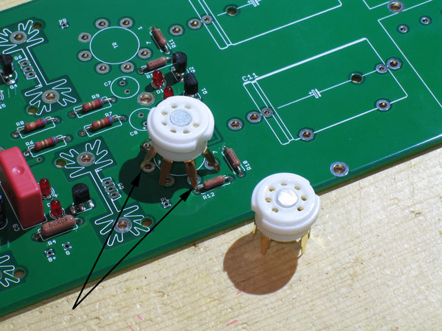
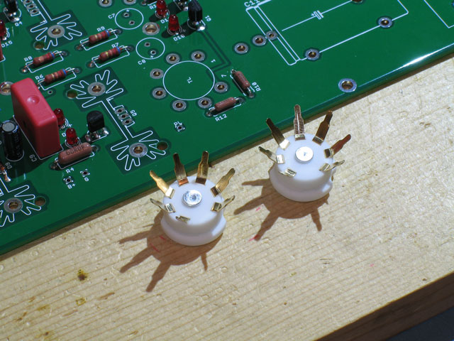
Step 13. - Tube sockets! No drilling for tube lighting here, though - too many high-voltage traces running under the sockets. That's OK, though, because the amp's PCB already has six LEDs that we installed in Step 8. We recommend the oft-used ceramic PCB tube sockets for the Torpedo as shown below - one wrapped as they come from the manufacturer and one unwrapped: Inspect your tube sockets carefully. I've seen some where the tube-pin holes were partially or completely covered by the molded ceramic. Next, I install my tube sockets a little differently than many. The sockets, their structural integrity, alignment and proper electrical connection are all important. You may end up plugging and un-plugging different tubes tens or perhaps hundreds of times. The sockets need to mounted properly to withstand that kind of fatigue. The electrical connection must be sound to minimize the effects of grounding issues. Finally, their alignment is also important to prevent permanently crooked tubes for the life of the amp. De-soldering one of these buggers is difficult, so proper preparation is key. So, I start by splaying out the sockets' PCB pins so that the circle they form is slightly over-sized compared to the PCB pads. Looking at the pic below, you can see that the PCB pins are bent outward so that they're just outside the PCB pads: IMHO, this forces you to slightly wedge the pins back inward, so that the fit is tight and secure - everything is pretty much locked into place before you apply the first solder. Here we can see both sockets with their PCB pins splayed out, just prior to placing into the PCB and soldering into place:
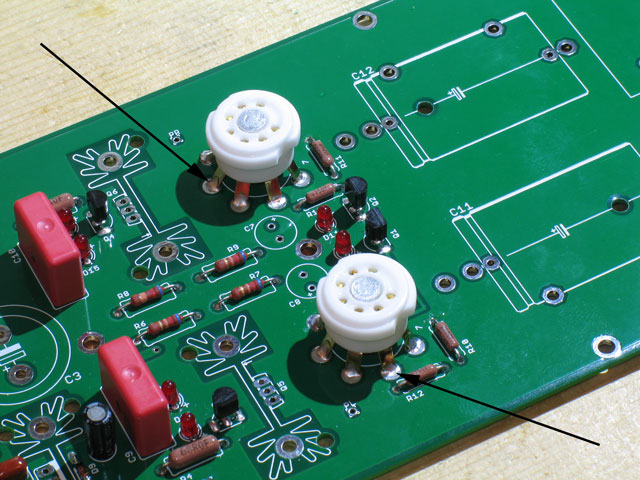
Finally, solder them into the PCB. As with previous mechanical-electrical solder connections, ensure that the pads are completely filled and that you get wicking some distance up the pins on the top side of the PCB: Note that the solder has wicked up at least 1/8" or so on each PCB pin leg. Turn the PCB over and apply solder to the top, if necessary, to ensure a good mechanical connection. While soldering on the backside of the PCB, treat the sockets as if you're tightening bolts on a spare tire - alternate soldering opposite pins until you've completed the circle. |
file last changed:Monday, May 27, 2024 12:25:38 PM
Please contact the TORPEDO webmaster for questions about these web pages.


