Pete Millett's Hybrid Headphone Amplifier (old history)
Go Back to DIYForums.orgLastupdate: May 27, 2024
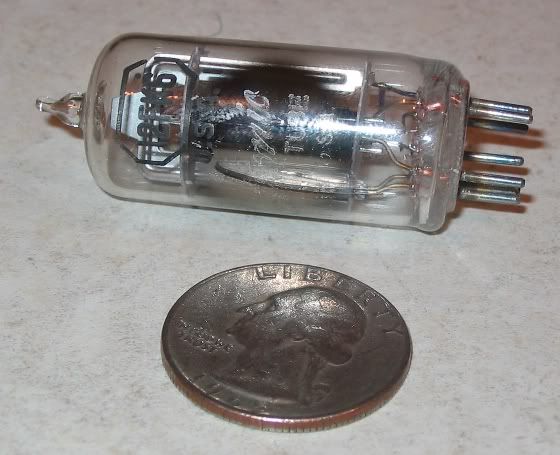
A few years ago, tube amplifier guru Pete Millett created a safe to build, reasonably priced tube headphone amplifier
based on the 12AE6A automotive radio tubes. They're known as space-charge tubes and designed to run on 12 volts instead of the
hundreds of volts of standard tubes. They were made for automobile radios before transistors. From a practical point of view, use of these tubes means that you can stick
your hands into this circuit and not run the risk of dying from electrocution.
The amplifier circuit that Pete created is a hybrid tube/solid state design. It uses the tubes as
votage gain devices and a Burr Brown OPA634 buffer as the output stage. It's an excellent idea
and one that was common in the brief period between the introduction of car radios and low-cost
transistors. Back in the day, those radios used a tube for voltage gain and a germanium
transistor as the output stage. In the case of the Hybrid Headphone Amp, the BUF634 serves
two purposes: to provide a current source for the headphones and to drop the output impedance
to a value low enough so that the amplifier does not need output transformers.
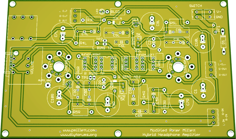
This implementation of the Hybrid Headphone Amplifier was inspired by DIYForums.org member
n_maher. Based on suggestions from Nate and others, DIYForums.org member drewd
adapted Pete's original design to fit on a standard double Eurocard form factor.
NOTE from Beezar Audio's TomB: "Since the MAX, MiniMAX, and MOSFET-MAX, we refer to this particular Millett Hybrid design as the "revMH Millett Hybrid."
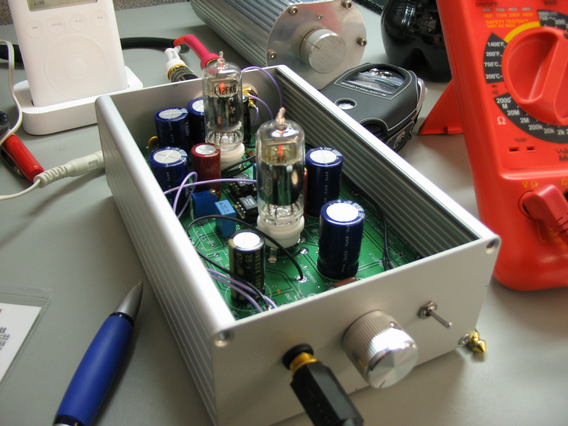
The result:
More Information
(Latest info comes first)
The Eagle CAD files as well as a full set of Gerber and Excellon drill files is available for anyone to have their own boards built. These files
represent the final version of the revMH PCB and you are free to use them for any purpose.
The Eagle CAD file is available here. An Eagle library with most of the parts used in the CAD file is
available here. A zipped archive of the Gerber and Excellon files is available here.
If the BUF634 is out of stock with your favorite
suppliers, you can substitute an OPA551 if you connect pins 2 and 6. It will not affect the performance of the BUF634 if you decide to use one later.
Eagle .brd and PCB manufacturing files are available here. You don't need any special permission
to manufacture the PCB, although I'm sure that Pete would appreciate an email to let him know that
you've made some. Further down the page is a link to the custom Eagle libraries that were used to
design the board.
The build instructions are a little out of date, but mostly just missing a few details. If you have a problem or a question, you can send an email to Beezar Audio's TomB.
The web-based BOM has been updated to provide part numbers for the new terminal blocks
for power and inputs/outputs. Part numbers are listed for the OPA551. A Neutrik headphone
jack can be directly mounted to the PCB.
Other improvements to the board:
- Additional buffer choice: Intersil's HA3-5002 buffer
- Positions for Kobiconn terminal blocks for input, output and power
- Removed alternate input, output and pot pads
- Reviewed and rerouted a few traces to tighten up the layout a bit
of the latest board.
The web-based BOM has been updated to provide an alternative to the BUF634 (which is
sometimes in very tight supply). The OPA551, a high current output opamp can be used
as a unity gain buffer in the same spot. You'll have to put a jumper between pins 6 and 2
to close the feedback loop. This won't affect the performance of the BUF634 if you want
to try one out later because pin 2 on that part is unused. Sonically, there doesn't seem
to be any difference between the chips.
If your PCB has a position for D3, please ignore it. D3 on the PCB is not used. There's no
need to put a diode there because D1 already fulfills that purpose. It has been removed
from the latest board.
Ti Kan (AMB in the forums) has posted some rather extensive performance measurements of
his Millett Hybrid amplifier. His comments at the end of the article provide a very
interesting contrast to the results of his measured data. Thanks Ti!
Preliminary build instructions are here!
The BOM has been updated to fix a couple of errors - the quantites for C9 and C10
were incorrect and a different 470uF cap has been specified for the Mouser sheet because
the original will be out of stock for several weeks.
Nate Maher has created a bill of materials, including part numbers and prices (in USD) in a
Microsoft Excel spreadsheet. You can download the spreadsheet here.
Along with the link to the board file below, a library file containing most of the parts used
in the board is available for download here. The only really significant parts that you may
not be able to find elsewhere are the 7 pin mini sockets, the ALPS Blue Velvet and the
Panasonic EV-J pots. The other parts are pretty common.
The final prototypes prior to production are in and being built. See one of the final prototypes in the picture above.
Alternate placement positions for J503 CRDs (an alternate for D2R and D2L) are on the board.
D2 should be populated with a 1N5291 or a J503 but not both.
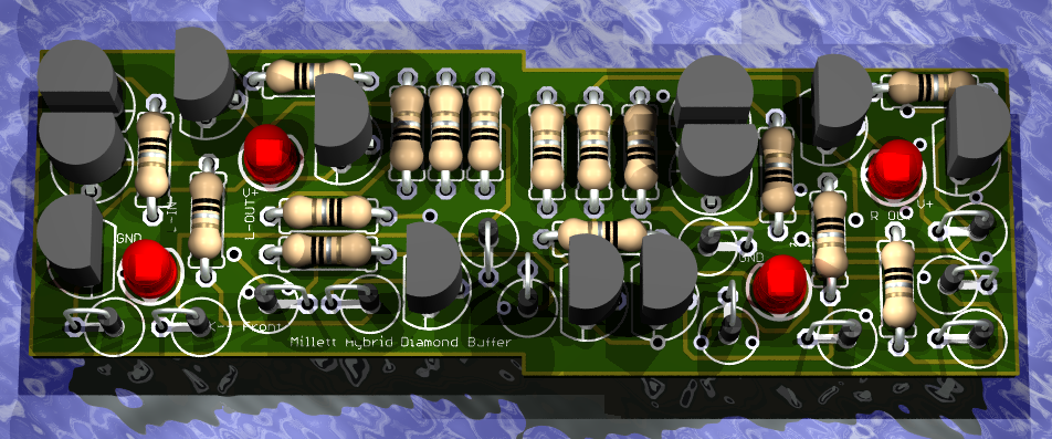
The diamond buffer board (no longer available) was developed and plugs into the BUF634 sockets:
Pete Millett's web page is here. It includes links to the schematic for the board, the original
AudioXpress article discussing the board and some Eagle board layout files.
Please note that the BOM posted on Pete's site and in the AudioXpress article has a
couple of errors in the part selections for the electrolytic caps. The proposed parts list
uses different parts from Handmade Electronics.
The preliminary build instructions
Current
parts list:
| Reference | Quantity | Description | Handmade Electronics | Welborne Labs | Digi-Key | Mouser | Notes |
| C1, C9L/R, C10L/R | 5 | ≥100uF electrolytic cap | Elna
Silmic II 3-RFS-10001000 (100uF) |
Elna
Cerafine ROA104 (100uF) |
Panasonic
FC P10348-ND (270uF) P10352-ND (470uF) |
Nichicon
UPW 647-UPW1J271MHD (270uF) 647-UPW1J471MHD3 (470uF) |
Voltage rating should be no less than 35V. 7.5mm pin spacing, 16mm diameter. Alternate pin spacing is provided for 5mm pins. |
| C7L/R | 2 | ≥100uF electrolytic cap | Elna
Silmic II 3-RFS-10001000 (100uF) |
Elna
Cerafine ROA104 (100uF |
Panasonic
FC P10348-ND (270uF) P10352-ND (470uF) |
Nichicon
UPW 647-UPW1J271MHD (270uF) 647-UPW1J471MHD3 (470uF) |
The
output coupling caps determine the low frequency cutoff
point.
For 100uF is the lowest recommended value. For headphones
with
impedances <150 ohms, up to 470uF is appropriate. 35V,
7.5mm
pin spacing, 16mm diameter. Alternate pin spacing is provided
for
5mm pins. |
| C2L/R | 2 | ≥220uF electrolytic cap | Nichicon Muze KZ 3-4030 | Elna Cerafine ROA220 | Panasonic
FC P10346-ND |
Nichicon
UPW 647-UPW1H221MPD |
Voltage rating should be no less than 16V. 5mm pin spacing, 10.5mm diameter |
| C3L/R, C4L/R, C5L/R, C8L/R | 8 | 0.22uF film cap | Wima MKP10 WM210 (0.10uF) | Panasonic Polypropylene P3224-ND | Wima
MKP10 505-M100.1/160/5 Xicon Metalized Polypropylene 1429-2224 |
Placements
provided for film capacitors with pin spacing of 5mm, 10mm and
15mm. See note below for alternate supplier. The Mouser Wima part is a 0.1uF capacitor. That's fine - the exact value is not important. |
|
| C6L/R | 2 | 0.01uF axial ceramic cap | 1103PHCT | 80-C410C103K5R | |||
| D1 | 1 | P6KE30 Transient Supressor | P6KE30ADICT | 511-P6KE30A | |||
| D2L/R | 2 | 1N5291 or J503 CRD | 610-1N5291 J503 |
Locations are provided on the board for the 1N5291 and the J503. Do not populate both diode types! Use either the 1N5291 or the J503, but not both. Also, do not mix and match - use two 1N5291s or two J503s, but not one of each. You've been warned... | |||
| PF1 | 1 |
RXE050 PTC Fuse | Raychem RXE050 | 650-RXE050 | |||
| RLED, R3R/L R5R/L | 5 | 1KOhm, 1/4W Resistor | Vishay Dale V4-1.0K | 1.00KXBK-ND | Vishay Dale 71-RN60D-F-1.0K | Any 1KOhm 1% 1/4W or 1/2W metal film resistor may be substituted | |
| R2R/L | 2 |
5KOhm Trimpot | Bourns 3296W | Vishay/Spectrol
594-64W502 |
|||
| R4R/L | 2 | 22 Ohm 1/4W Resistor | Vishay Dale V4-22.0 | 22.1XBK-ND | Vishay Dale 71-RN60D-F-22.1 | Any 22 Ohm 1% 1/4W or 1/2W metal film resistor may be substituted. Take special care to be sure that you do not accidentally order a 22.1KOhm resistor from Mouser - the part numbers are nearly identical. | |
| R6R/L | 2 | 220 Ohm 1/4W Resistor | Vishay Dale V4-221 | 221XBK-ND | Vishay Dale 71-RN60D-F-221 | This sets the bandwidth of the buffers. Theoretically, it can be jumpered, but this will increase the current demands of the buffers with little sonic benefit. These resistors are optional. | |
| VT1, VT2 | 2 | Tube | See notes below | ||||
| Tube Sockets | 2 | 7 Pin Mini Socket, PCB Mount | See notes below | ||||
| Terminal Block | 2 | 2 Position Terminal Block | Kobiconn
158-P02EK381V2 |
Optional for power and switch connections | |||
| Terminal Block | 1, 2 or 3 | 3 Position Terminal Block | Kobiconn 158-P02EK381V3 |
Optional for input and output connections | |||
| Headphone Jack | 1 | 1/4 inch | Neutrik NMJ6HCD2 550-22302 |
||||
| Buffers | 2 | 8 Pin DIP Current Buffer | Burr
Brown BUF634P-ND Burr Brown OPA551PA-ND |
Burr
Brown 595-BUF634P |
Pads
are also provided for Intersil HA3-5002 buffers available from Arrow Electronics. If you use
the OPA551, you MUST connect pins 6 and 2. Do not stack the
OPA551. |
||
| Buffer
Sockets |
2 | 8
Pin DIP Socket |
Assmann Electronics AE7313-ND | Mill
Max 575-113308 |
Any
standard 8 pin DIP socket will work here. This optional - you can
solder the buffers to the board. |
||
| Pot | 1 | 50KOhm Pot | Panasonic EV-J P2T3503-ND | Pads are also provided for ALPS RK27 "Blue Velvet" potentiometer | |||
| Power
Supply |
1 | 24VDC,
400mA |
CUI-Stack
DPD240040- P6P T5020-P6P |
Elpac
FW1824-760 680-FW1824-760 |
24VDC
- 30VDC, 400mA (min) |
||
| DC
Jack |
1 | 2.5mm
barrel |
CP-6-ND | Kobiconn 163-1100 |
There
are a plethora of choices. Make sure that your DC jack
matches
the power supply plug |
||
| Enclosure |
1 | Hammond
1455N1601 546-1455N1601 |
1601
has metal end panels, 1602 has plastic end panels. Add
letters
"BK" for a black anodized finish. Also stocked by Newark and
Allied |
||||
Additional parts are a headphone jack, input jack(s), power switch and volume knob (1/4" or
6mm shaft diameter for the recommended pots).
A slightly different, but every bit as good BOM is in a Microsoft Excel spreadsheet.
Notes on Tubes
Tubes that are known to work with this amplifier include the 12AE6A, 12FK6 and 12FM6. Pete's
original design used the 12AE6A. All three tubes are available online from various vendors,
including Tube Depot, The Tube Store and VacuumTubes.Net. They also carry the miniature 7 pin PCB mount
sockets.
Tube Data Sheets
| Manufacturer |
Part
Number |
| Tung
Sol |
12AE6 12AE6A 12FK6 12FM6 |
| General
Electric |
12AE6A 12FM6 |
| Sylvania |
12FK6 |
Buffer Data Sheet
| Manufacturer | Part Number |
| Burr Brown | BUF634 |
| Burr Brown | OPA551 |
| Intersil | HA2-5003 |
Note on Capacitors
If you're on a budget, you may find that the Elna and Wima caps are a little pricey. They are
considered boutique caps by many. The Panasonic, Nichicon and Xicon caps that are also
listed are perfectly fine alternatives. For a middle of the road configuration, consider using those
less expensive caps and use the boutique caps in positions C7L/R and C4L/R. Those are the
audio output coupling caps and the audio signal passes through them. The better the cap, the
(potentially) better the sound. For C7L/R, the capacitance value, along with the headphone
impedance, sets the low frequency cutoff value. The larger the capacitance, the lower the frequency.
100uF is the lowest recommended, 470uF is probably as high as you need to go.
For power ratings, 35V is sufficient for any of the electrolytic caps. Higher power rating
gains no advantage.
An alternate source for the Wima capacitors is TAW Electronics. Their prices are similar to Mouser's
They do not have a web ordering interface, but do take orders via email and phone.
Power
An excellent choice for powering this amplifier is the STEPS linear, regulated power supply.
PCBs and instructions for building the power supply are available on Tangent's web site.
It fits the same size Hammond case as the amplifier.
Enclosure
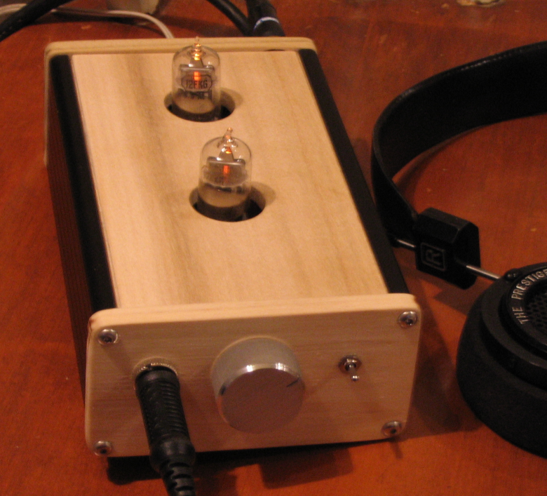
The Hammond 1455N1601 enclosure is not tall enough to competely contain the tubes, so if
you are using it, you will have to drill holes in the top for the tubes to extend through. Drew's prototype
amplifiers positioned the circuit board about four slots up from the bottom of the case so that
the volume control would be centered on the front panel and so that the tubes would be almost fully
visible outside of the case. The best way to drill the holes is to use the "belly plate" of the case
as the top, position the circuit board on the plate and mark the hole locations with a pencil.
A 1" hole will allow clearance for the tubes. A stepped drill bit is highly recommended.
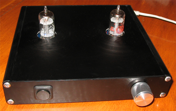
As seen above, Hammond's 1455R2201 enclosure will also work, if you use the alternate
Panasonic FC caps - they're quite short, so they've fit in the 1.2" tall case. An ALPS Blue
Velvet pot will not fit that case, though.
Other people have built these amplifiers in Par-Metal 20 series cases which are
large enough to contain both the amplifier and STEPS circuit boards. Here's dsavitsk's:

Vendor Web Sites
Handmade Electronics
Welborne Labs
Digi-Key
Mouser
TAW Electronics
Par-Metal
Tangent's Parts Shop
Purchasing the boards
Boards are available here.
Both drewd and n_maher can be contacted via PM on DIYForums.org
Pete Millett graciously gave us permission to tear his original board to shreds - THANK YOU!
Nate Maher (n_maher on DIYForums.org) organized this whole thing!
Drew Dunn (drewd on DIYForums.org) redesigned Pete's work. Blame him if it doesn't work!
A special thanks to those who contributed excellent ideas and suggestions:
comabereni
bg4533
blip
MisterX
dsavitsk
Nisbeth
vksy
individual6891
slindeman
skyskraper
guzzler
sijosae
sbelyo
flecom
buzzerbro
amb
AtomBoy
Finch&Music