Buy Boards & Parts:
www.beezar.com
www.beezar.com

The Starving Student Millett Hybrid PCB
Construction - PCB, Part 3
|
Let's finish off the PCB!
|
|
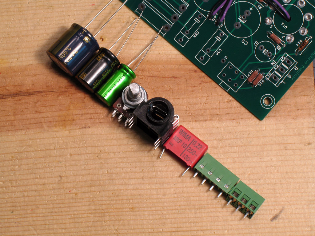 |
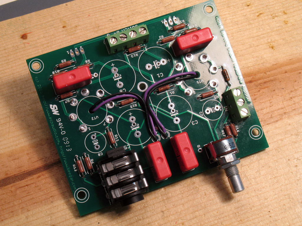
9. Check the Relative Heights of the Remaining Parts - Here we see all the rest of the parts, except the MOSFETs, laid out into a row, according to height. Note the order - this is how we'll finish the rest of the PCB - shortest to tallest, until they're all done. Things get FUN, now. |
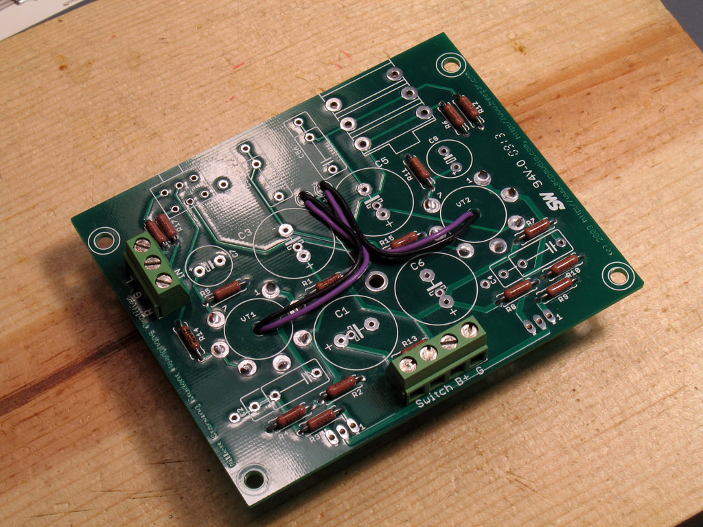 |
10. Solder the Terminal Blocks in Place - As with all that's gone before, place the parts in the proper pads, turn the board over and press down slightly while soldering the leads. In the case of the terminal blocks, the pins have a lot of slack in the holes. (This is by design - it's critical that the pins make good contact with the board and you have no control over wicking.) |
| I like to solder one of the interior pins, first. The blocks seem to rotate better on one of the center pins. I've soldered one of the ends first, found out it was misaligned, but then lacked enough slack to turn the block straight. So - small caveat - but generally easy enough to solder. Some caution is needed because the blocks are plastic. It's possible to apply enough heat that you can melt them.
Be sure you have the openinings toward the outside of the PCB! 11. Solder the WIMA Film Capacitors In Place - There's four of them and they're easy enough to place in position. However, the leads are thick and short - they don't stick the parts in by themselves. If you're using the pine board like me, though, there's a trick:
|
|
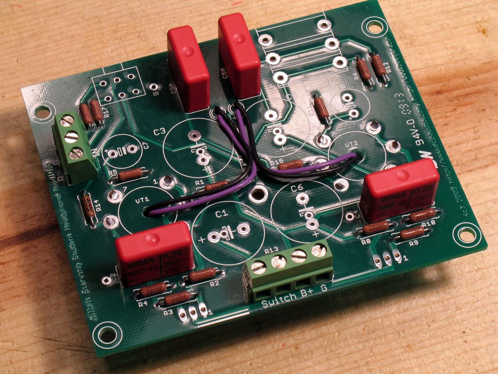 |
You'll find that the Wima's are so square and so evenly placed on the PCB that the entire PCB is supported in a straight and level position while upside down - nothing could be easier! Don't forget - like everything else - solder one lead on each Wima while pressing down slightly to ensure that they're flush. Note that there are little tabs on the bottom edge of the Wima's, so "flush" will still mean there's an air gap underneath. Then flip the PCB back over and make sure they're not crooked. Straighten them gently, if necessary. Flip the PCB back over onto the pine board and finish the soldering. Trim the leads when you're done. |
| Note: I don't trim the leads on anything else but the capacitors - the terminal blocks, volume pot, and headphone jack are left un-trimmed. | |
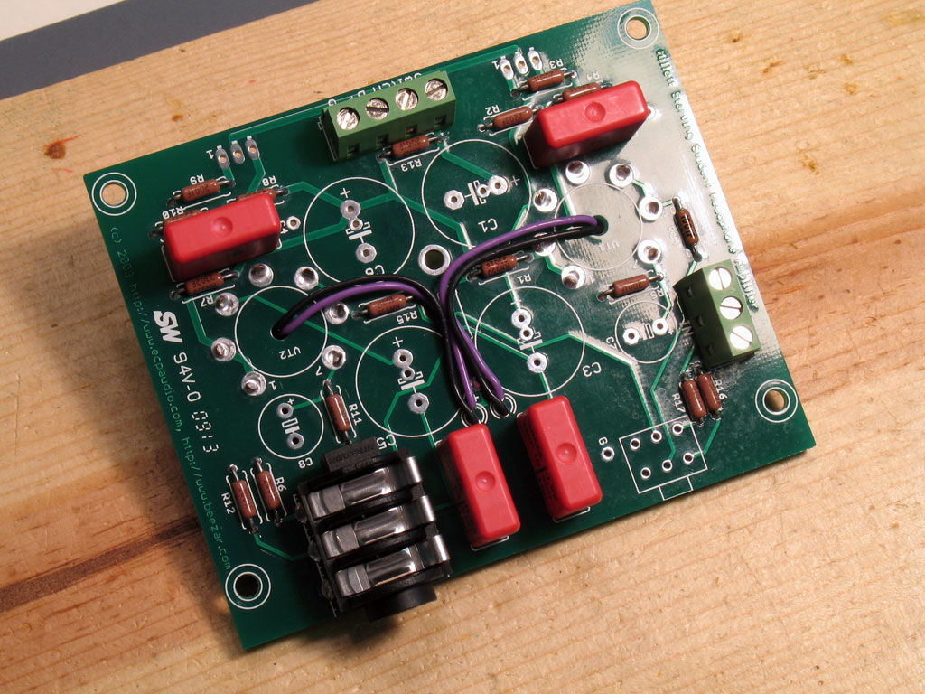 |
12. Solder the Headphone Jack in Place - Straightforward, but you'll have to press the PCB down and keep things lined up while you solder the first couple of pins. That's because there's no headphone jack on the other side of the PCB to even things out. |
Use the same method for soldering the headphone jack as you did with the tube sockets:
|
|
 |
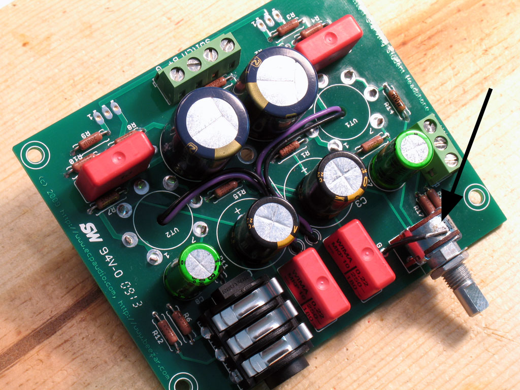
13. Solder the Volume Pot Into Place - The pins and pads are small on the volume pot, so it's much easier to keep the pot aligned while soldering. However, it's short from front to back, so it's pretty easy to get the shaft pointing a bit down or up. This will drive you crazy when you try to set the volume knob in position, so do your best to get the pot shaft parallel to the PCB. Solder a couple of the back pins (leave the ground pins for last), then check the alignment. Press down in back or in front, depending on what's needed to keep the shaft aligned. Also check the side-to-side alignment, too. A little care doing all of this will payoff when you go to set the knob in place. |
| Otherwise, the knob may scrape at different positions in volume travel. You may end up with a large gap to keep it from scraping, which may not look aesthetic. | |
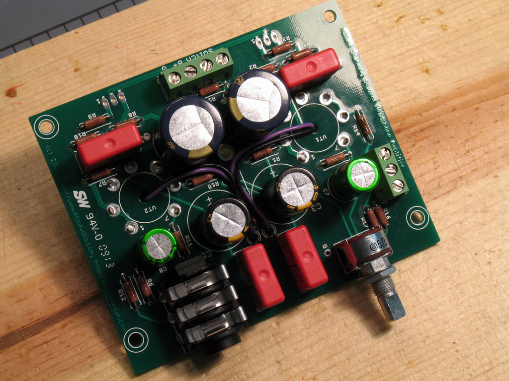 |
14. Solder the Electrolytic Capacitors in Place - This one's easy and fun to do! Note from the first pic up there that all of the electrolytic capacitors we've supplied for you in the kit are all the same height! So, we'll want to place everyone of them on the board at the same time, pick up the pine board, turn it upside down while placing it on top of the caps on the PCB that we're holding in our other hand, and do our reverse patty-cake maneuver. Be sure you have them inserted in the proper pads, though. All the long leads go into the holes marked "+". |
|
As with the Wima's, the electrolytics completely support the PCB in a straight and level position. Solder the leads - as always, solder one of each for all of them, flip the PCB over and ensure that there's no mis-alignment. Finish all of the soldering and then trim the leads. (I don't trim the leads on anything else except the Wima's. The terminal blocks, headphone jack, and pot all stay untouched.) There is one last tweak we'll do to the PCB before we move on to the case assembly. It's soldering a small lead from the "G" pad to the metal body on the volume pot. This will remove any ground hum you might hear when grabbing the volume knob to adjust the sound level. I'm not sure that pot hum is an issue with this pot, but it won't hurt anything and will ensure that the issue never comes up. We'll do that next and then assemble the case!! | |
 |
15. Solder the Ground Wire to the Volume Pot - This will essentially complete construction of the PCB except for the MOSFETs, which we'll leave for fitting up with the case lid. Trim a wire so that its length is sufficient to curve over the top of the volume pot from the "G" pad on the PCB. As always, tin the tips of the wire with solder. Strip one end slightly - that one will go into the PCB pad. Strip the other end so that about 1/4" is exposed. That will leave plenty to solder to the metal body of the volume pot. |
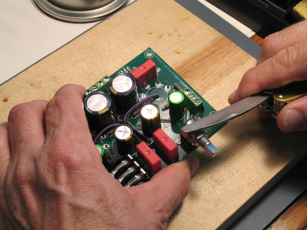 |
The metal body of the volume pot has a finish to it that will inhibit sticking with solder. So, we'll file the top a bit so that the solder will have something to stick to - |
 |
Once we have a patch filed, it's time to solder the ground wire in place - |
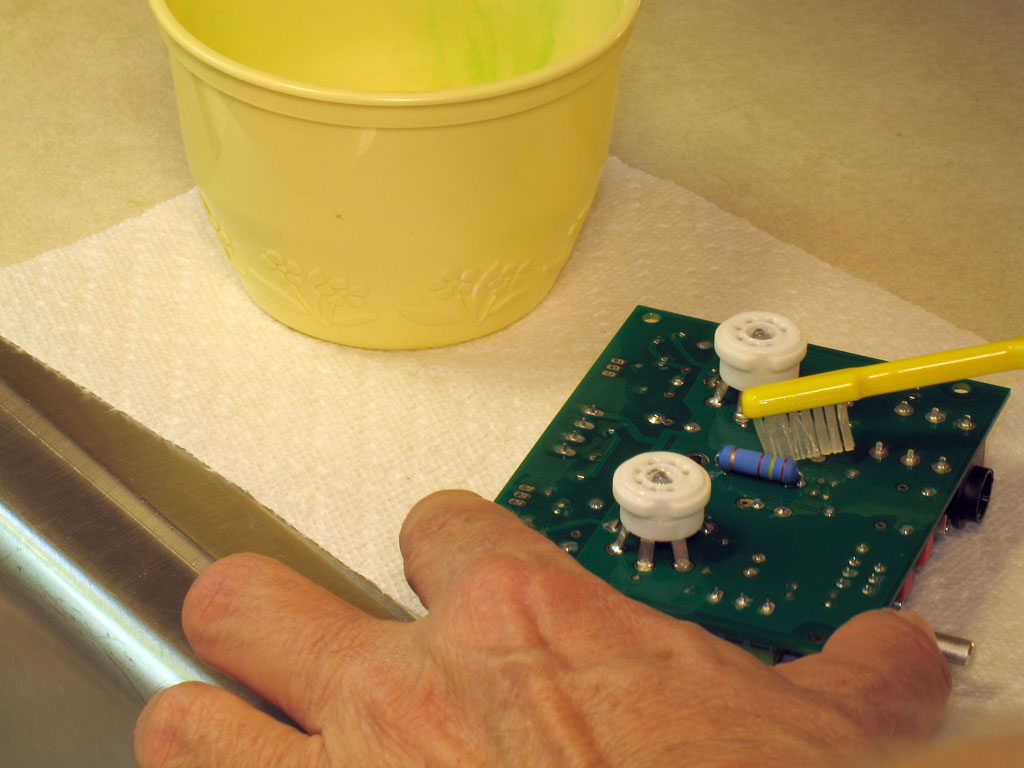 |
16. Clean the PCB of Flux - At this point - as noted earlier - we're basically finished with the PCB. So, let's clean it thoroughly. I'm a cheap-skate on some things and cleaning solder flux is one of them. Basically, I use some 90 cents a quart, Walmart 90% isopropyl alcohol as the rinse. I pour some in an old plastic butter bowl and use an old toothbrush and a paper towel. |
| It took me about 5 or 6 rinses, using a paper towel to pat off the alcohol/dissolved flux to get it acceptably clean. There may still be some white spots around the solder joints, but I'm not that picky. | |