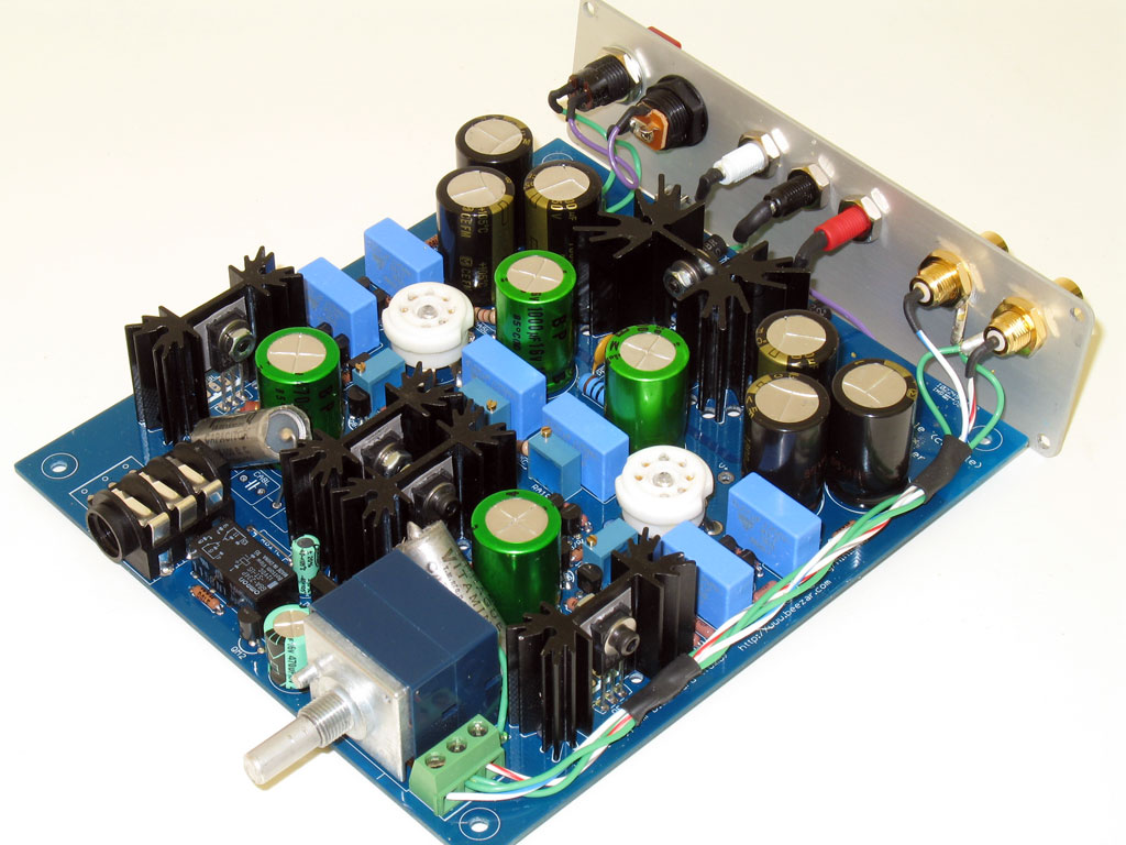
So you've built a MiniMAX and are ready to wire it up and assemble it in the custom Beezar/Lansing case. Congratulations! You'll find that with a few wrinkles, wiring up the MiniMAX and assembling the custom Beezar/Lansing case is a snap. Chances are, the wiring is as easy or easier than with many DIY headphone amplifiers. As for assembling the case - nothing is easier. All the holes are drilled and the case is finished off with silkscreen labeling on front and back. You only need assemble the connectors into the right place to provide a professionally-manufactured appearance to your DIY work.
There are a couple of items you need to watch out for:
1) There is very little room left in the case once assembled and So, trim your wiring to fit where possible, and
2) you'll need to scrape around some of the holes (from the inside, of course) in order to make the best contact for proper grounding.
The custom Beezar/Lansing case was anodized after machining for the best possible apperance. So, the case metal is insulated from making any electrical contact with scraping down to the bare metal.
Wire - 22 gauge, teflon-coated multi-strand wiring is the best choice for wiring up your MiniMAX. The teflon coating is quite heat-resistant and allows you to solder without the insulation shrinking up and pulling away from the solder joint, as happens with almost all typical hook-up wire sold at Radio Shack and elsewhere. Silver-Plated Copper, teflon insulated wiring is available from John's Silver Teflon Wire Shop on ebay. It's the only wire I use in building. You can get similar wire elsewhere, but very often you'll have to purchase it in much higher quantities. Get three different colors from John and it will last you for several years of DIY projects. Note that his stock varies from time-to-time, but send him a note and he may be able to accomodate your needs.
Of course, SPC-teflon coated wiring is also available at many other sources - Handmade Electronics (by the foot), Mouser, DigiKey, etc. In addition, you'll need some tools for wiring:
Wire strippers for 22ga wire
Heat Shrink Heat Gun
Scissors for cutting heat shrink.
Don't skimp on the wire strippers - you'll regret it. Still, it's not necessary nor is it desireable to buy one of those huge, automatic strippers. Just get a manual one that's of good quality and learn how to use it. Luckily, these things are in enough demand that you can find very good quality ones at Lowe's and Home Depot, among other places. I use a pair of Kleins that are good for 16-26ga wire. You should be able to get a pair of these for $20 or less. They both cut and strip wire, but it's all manual - nothing fancy - but reasonable quality (don't buy a pair from Harbor Freight, in other words) ensures that they make good cuts and stay sharp. At the same time, the simplicity and small size lets you get into smaller places, which is sometimes a convenient feature to have with our type of projects.
On the other hand, Harbor Freight is the ideal place to purchase a heat gun for shrinking heat shrink. You can get one for less than $15. There's no need to go quality in this case - you only need something to blow heat on a piece of heat shrink for 5-10 seconds. I purchased one similar to the pic at right a few years ago. Even though some pieces have broken on it now, it's more than adequate to melt the tiny heat shrink that we use for hookup wiring (3/32" - 1/8"). BTW, you can also get heat shrink at Lowes or Harbor Freight. You may find the Lowes options a bit more convenient. The size heat shrink I use most often is 3/32". Harbor Freight has a good, cheap selection, but most of their stuff comes in assortments and you'll end up with a lot of larger sizes that you'll never need.
Wiring Watchwords -
Start with lead lengths longer than you think necessary, then trim to fit to make the final connection.
Tin the ends with solder after trimming and stripping. The one exception to this is the Volume Pot Ground Wire. If you tin the tip, it will become too hard to bend around the pot screw and prevent screwing the screw back in.
Use heat shrink to insulate all soldered connections except for ground wires. Since the entire case should be grounded, it's OK to leave those without heat shrink. Note that the entire power input/power switch is AC, so all wires should be insulated/heat shrinked.
Be sure to scrape down to the bare metal on the inside of the back plate where the RCA jacks contact. This will ensure that the signal wires are grounded to the case.
Scrape a bit around the center standoff hole opening on the inside of the case. The standoff hole on the PCB is grounded to the PCB's ground plane. When you scrape the case hole on the inside, this will ensure that the PCB ground plane makes contact with the case through the center standoff.
Finally, if you believe in after-market cabling and differences in sound with different types of wire, then you may want to leave the tips un-tinned for the RCA-signal wiring. If you're using SPC (Silver-Plated Copper) wire, then leaving them un-tinned will allow the SPC wire to make direct contact with the input terminal block (next to the pot). I lightly tin mine anyway, just to prevent fraying and making a mess, but it's up to you.
Wiring Requirements
The wiring requirements for the MiniMAX are quite simple and as follows:
Power Switch
Power Socket
RCA Jacks
Tip Jacks
Volume Pot Ground Wire
NOTE: Pics with wood countertop provided by user "Beefy."
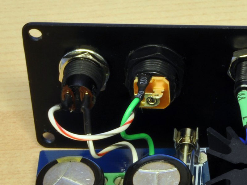
1. Power Switch -
The power switch takes a shortcut with the center-positive wire from the power socket. Wire the center-positive wire from the power socket directly to one lug on the SPST switch. This will be a very short wire, perhaps 2", only enough to let you loop from the power socket to the switch.
After that, a wire from the other lug on the SPST switch, along with a wire from the outside-negative lug of the power socket, becomes your two power inputs to the terminal block on the board. Again, these will be relatively short (but not as short) - perhaps 3", but even then, they will probably be looped by the time you get the backplate screwed on.
2. Power socket -
See the above. Seriously, the power socket and power switch are intertwined. One lead from one and a lead from the other form the two leads that make the power connection to the board. The remaining lug on power switch and the remaining lug on the power socket are connected together with a short lead. The BOM-specified power socket actually has three lugs. One of these is not used. Study the pic to determine which ones you need to use, or use your meter when after connecting the walwart to make sure you know which ones are "hot."
Also note the key plan at right - this shows which terminals to use, depending on whether you want to use the fuse for walwart protection. The fuse shold be a 1.0A Slo-Blo,. 5x20mm type. The polyfuse connecting the Power Supply to the rest of the circuit on the board actually protects the amp and buffer circuits themselves. The fuse provides protection for your walwart. Some walwarts do not have re-settable fuses, so when tripped, become worthless. The MiniMAX fuse will help to prevent that.
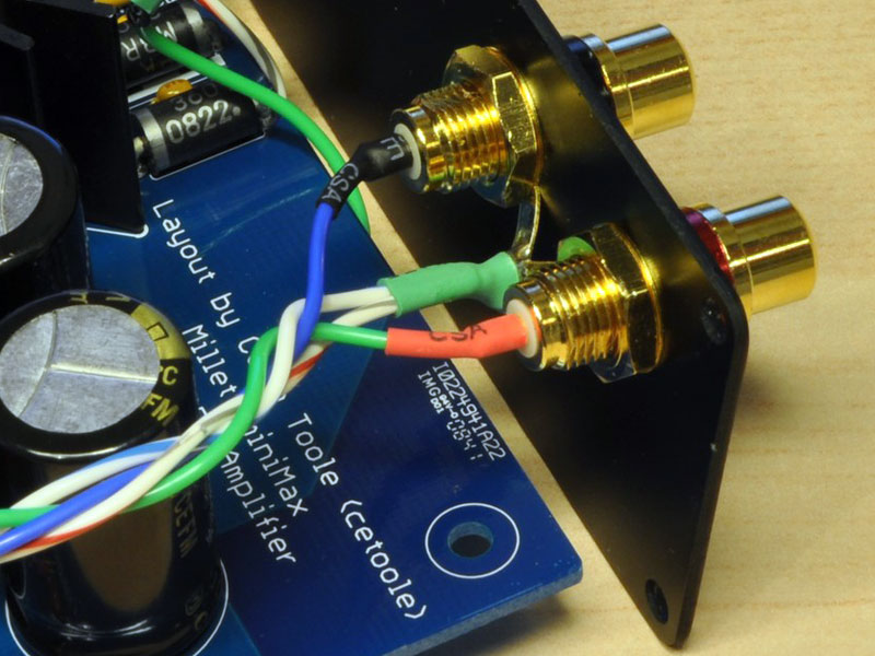
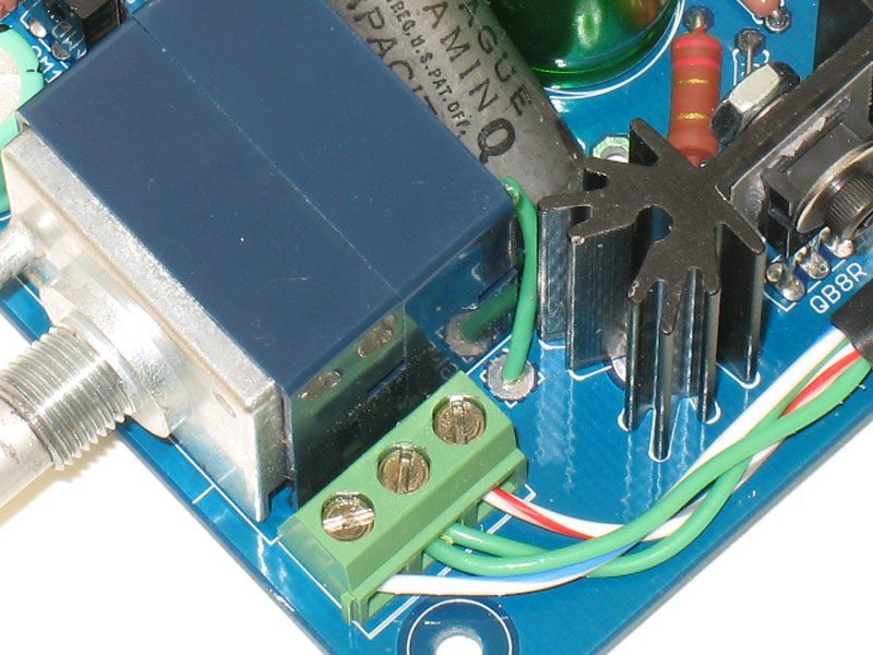
3. RCA Jacks -
Here we ask that you run two ground wires, then one signal wire each. You should have a ground wire connected to the tab of each RCA jack. Plus, you'll have a Left signal wire connected to the center of the Left RCA jack and a Right signal wire connected to the center of the Right RCA jack. This gives you four wires, total.
Since these wires run the length of the board to the terminal block next to the pot, we're asking that you braid them into a Litz braid or similar. This is fairly easy to do, just cross the middle two Ground wires, then cross the two outside signal wires over to the center. Bring the now outside Ground wires to cross over to the center again, and repeat for the signal wires and so on. This is not truly a "Litz" braid, but it's good enough to minimize potential interference.
Run these wires long - perhaps 8 ". Wait until you're read to screw on the backplate, make a 90 degree bend in the wiring so as to connect into the terminal block, and trim to the proper length. Try to keep as little slack from the endplate as possible, because there's no room to loop this braided wire bundle like the power wires.
This is probably the only tricky part of the wiring - making sure you cut this bundle to length with the proper bend at the terminal block, leaving as little slack as possible at the endplate so the case can be buttoned up. Note that user "Beefy" ran his signal bundle up high. I run mine along the surface of the PCB at the bottom (in the pic at the top of the page) - either one is fine, but make sure you don't obstruct the heat sinks at top - that's where most of the heat rejection takes place. A couple of pieces of heat shrink on the wire bundle will help keep the braid intact.
One other note with the RCA jacks:
For the MiniMAX, it's best to have the RCA jacks grounded to the case. There's no danger of a ground loop, because the AC input socket is isolated from the case. However, the custom-machined Beezar/Lansing MiniMAX case is anodized after machining, so there are no bare metal spots. Consequently, take your handy pocket knife or something similar and scrape a small patch down to the bare metal on the inside of the backplate around each RCA jack hole. It doesn't have to be much - maybe 1/4" square or something similar - just enough so that you are certain the inside nut of each RCA jack is clamped down on bare metal inside. Of course, don't worry about it if it looks bad, no one will see it.
4. Tip Jacks -
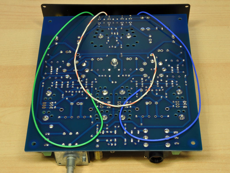
In this case, since the wires will be hard-soldered to the board, we recommend that you leave some slack. So make them long enough to reach the test point underneath the board, after looping forward and back, or something similar. This will help you in disassembly in the future, should that become necessary. You will have three wires from three tip jacks. Ground is the center tip jack, then left is Left and right is Right. The Ground tip jack lead should be soldered underneath the board to the "Gnd" test point near the power supply. The Left tip jack lead should be soldered to the "TA2L" test point under the board and the Right jack lead soldered to the "TA2R" test point.
The space under the board should provide plenty of room for the slack, but be wary of the wires catching in the slots that the PCB slides in. How much slack you need is your own judgment call.
There are three of these. One for Ground, and one each for the Left tube bias point and the Right tube bias point. These can be a bit tricky, too. As it turns out, the recommended tip jacks will impinge slightly onto the PS heat sink (they're a tad too long). So, you may need to bend down the wire joint slightly. The idea is to solder a long lead wire into the tip jack socket, then loop the leads from each down and under the board. There's enough room to do this because the PCB is actually about 1/4" from the edge of the back of the case (the PCB is flush in front). This space allows you enough room to bend the wires down and route them under the board.
5. Volume Pot Ground Wire -
This is actually easier to do before you've installed the heat sinks on the board. If you didn't do it then, then solder the ground wire to the Volume Pot now. Begin by cutting a lead length much longer than needed to reach the pot screw as shown. Solder the lead into the board, then bend and trim to length. I've cut it pretty short in these pics, but it's OK to have a much larger loop.
Also, as mentioned earlier, if you tin the tip on this wire, it will become too hard to bend around the pot screw and prevent screwing the screw back in. You should be able to screw the pot screw all the way back in. Notice the four holes in the front metal facing of the pot - these are the same screws and this is where the threads are. So unless you are able to push/screw the screw all the way back in, it won't make proper contact with the pot front plate. The front plate actually forms the bulk of the body of the pot, meaning connecting the screw back through to this plate is important to make the best ground connection.
Assembly
Assembly is straightforward:
Attach all leads to from the backplate to the terminal blocks on the PCB (the tip jacks should already be soldered underneath)
At this point, I like to install the center standoff. If you use the Beezar Center Standoff Kit, this is a snap. Use the longer screw, a washer and a lock washer to attach the standoff to the PCB. (The standoff goes between the bottom of the PCB and the bottom of the case.) Use of the lock washer on the PCB will prevent the standoff from becoming loose on the inside, a potentially frustrating occurence, since you can't access the standoff from the inside once it's screwed to the case. So make sure it's tight to the PCB.
Slide the PCB into the case from the back, in the bottom slot. Ensure that the signal input wire braid doesn't bind.
While the endplates are still loose and disconnected from the case, line up the center standoff with the hole on the bottom of the case. Install the remaining (the shorter screw in the Beezar kit) with a washer to from the outside of the case to the standoff. This locks the PCB in place in the case.
Install the front plate. The PCB should be flush with the front edge of the case body, but check to make certain this is so. If not, check the center standoff to be sure it's installed correctly. Note that the headphone jack hole in the front plate should slide over the headphone jack without any spacers. Install one spacer and the finishing spacer in front of the endplate, then the threaded ferrule. Leave loose until you do the rest.
Ensure that the locating pin for the pot fits through the provided hole in the front plate. Place the washer and pot shaft nut on the outside of the endplate and tighten down, but leave loose.
Gently finger screw in the self-tapping screws at the four corners. Alternate from one corner to the other until they're all tightened down.
Tighten the headphone jack nut and the pot nut. The headphone jack nut should be tight, but remember that you're also tightening down on the plastic spacers, so they won't take a heavy hand. Same for the pot nut - it's not really designed to be torqued down with a breaking bar - fit and snug is fine.
Install the four screws and the back plate in a similar fashion. Ensure that the wiring is not binding and that the tip jacks are not binding agasint the power supply heat sink.
If needed, trim the pot shaft. If you're using one of the 30mm ebay-Partspipe knobs (recommended), you'll need to trim about 1/4" from the pot shaft. I do this last, once I'm certain the front plate is in the position it will permanently remain. An easy way to trim the pot shaft using a Dremel cutoff tool is to use a 1-gallon ziplock back. Cut a tiny hole on the bottom edge of the ziplock, about an inch or two from the center. This will be the hole for the pot shaft. Place the amp in the bag, with the back of the amp toward the "ziplock" and close. The pot shaft should be sticking out of the small hole you cut in the bottom. Use some tape to seal this hole around the pot shaft and proceed to trim the shaft with the Dremel. Remove the MiniMAX from the bag when finished and clean up any residual metal filings around the pot shaft.
Install the knob.
Finally - stick on the four bumpers on the bottom - you're done!
file last changed:Tuesday, November 6, 2012 6:00:00 AM
Please contact the MiniMAX webmaster for questions about these web pages.

 The power switch takes a shortcut with the center-positive wire from the power socket. Wire the center-positive wire from the power socket directly to one lug on the SPST switch. This will be a very short wire, perhaps 2", only enough to let you loop from the power socket to the switch.
 In this case, since the wires will be hard-soldered to the board, we recommend that you leave some slack. So make them long enough to reach the test point underneath the board, after looping forward and back, or something similar. This will help you in disassembly in the future, should that become necessary. You will have three wires from three tip jacks. Ground is the center tip jack, then left is Left and right is Right. The Ground tip jack lead should be soldered underneath the board to the "Gnd" test point near the power supply. The Left tip jack lead should be soldered to the "TA2L" test point under the board and the Right jack lead soldered to the "TA2R" test point.
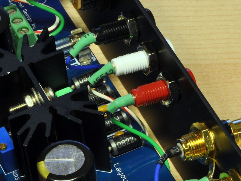 There are three of these. One for Ground, and one each for the Left tube bias point and the Right tube bias point. These can be a bit tricky, too. As it turns out, the recommended tip jacks will impinge slightly onto the PS heat sink (they're a tad too long). So, you may need to bend down the wire joint slightly. The idea is to solder a long lead wire into the tip jack socket, then loop the leads from each down and under the board. There's enough room to do this because the PCB is actually about 1/4" from the edge of the back of the case (the PCB is flush in front). This space allows you enough room to bend the wires down and route them under the board.
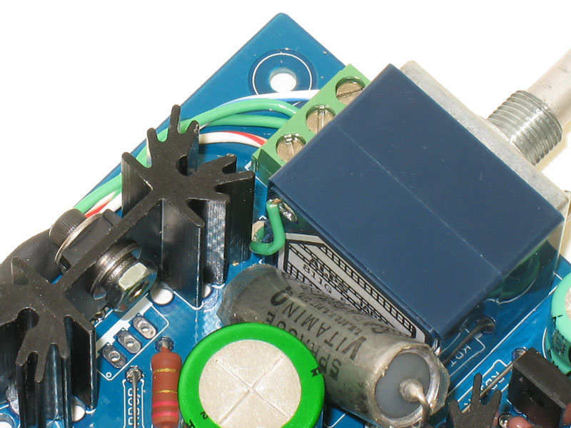
 I use a pair of Kleins that are good for 16-26ga wire. You should be able to get a pair of these for $20 or less. They both cut and strip wire, but it's all manual - nothing fancy - but reasonable quality (don't buy a pair from Harbor Freight, in other words) ensures that they make good cuts and stay sharp. At the same time, the simplicity and small size lets you get into smaller places, which is sometimes a convenient feature to have with our type of projects.
  I purchased one similar to the pic at right a few years ago. Even though some pieces have broken on it now, it's more than adequate to melt the tiny heat shrink that we use for hookup wiring (3/32" - 1/8"). BTW, you can also get heat shrink at Lowes or Harbor Freight. You may find the Lowes options a bit more convenient. The size heat shrink I use most often is 3/32". Harbor Freight has a good, cheap selection, but most of their stuff comes in assortments and you'll end up with a lot of larger sizes that you'll never need.