www.beezar.com

Colin Toole creates the Millett MiniMAX -
In late Spring/Early Summer 2008, Colin Toole and I began discussing the early prototype Millett Hybrid MAX. I had been encouraging Colin to pursue the smaller board design that harkened back to this original MAX prototype. It had been designed to use the Lansing-Enclosures MicroPak C enclosure. However, after addressing the early issues with the power supply (hum and ripple), the group buy/production MAX board had been upsized to fit the Hammond case and the rest was history (MAX history). However, I continued to use the uncased and "modified" first prototype MAX as my everyday home amp. |
 |
| After building a number of MAXes, it seemed that my modified original prototype MAX had slightly better detail. Moreover, a second prototype - actually the first "MiniMAX" prototype - had a similar characteristic. Colin and I began a series of long discussions about why that might be so. The original MAX prototype had a power supply ground plane that was contiguous with the ground plane for the rest of the PCB. Unfortunately, we found that this corrupted the signal with both AC hum and ripple. At the time, I solved the audible hum and ripple by breaking the power supply rectifiers and electrolytics off of the board. In other words, all AC components were removed from the board proper. (We had tried a few other methods along the way, too.) Offloading the AC components had the effect of removing hum and ripple below audibility. This same "piece-meal" early prototype MAX was my everyday home amp. |
|

|
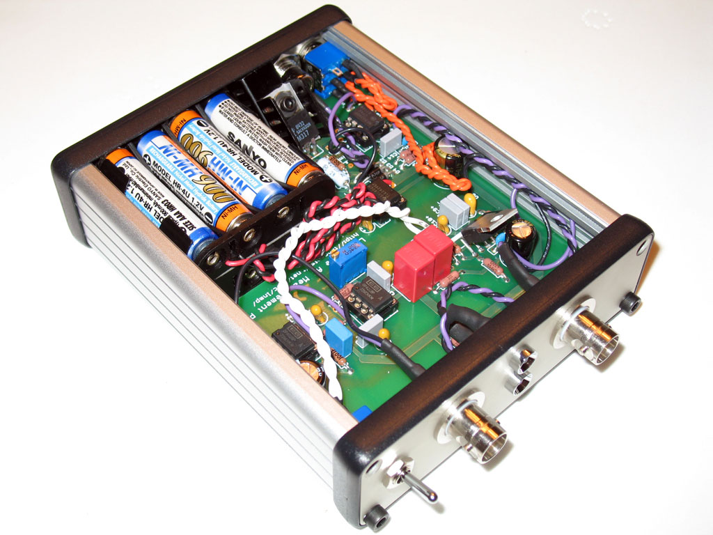
Looking at left, you can see how the rectifier string and ps electrolytics were offloaded onto a piece of perfboard. (Note earlier cuts in the board that were unsuccessful at removing the ripple.) As stated, this removed all audible traces of hum and ripple. The amp had an impressive all around sound with great detail. I continued to use this amp as my home amp until recently. We drew the conclusion from this prototype board surgery that the ground plane was the culprit. |
|
So, the production MAX PCB's were designed and produced with no ground plane under the power supply section. The PCB was a great success (see MAX History) and over 500 boards were sold to places in the US and all over the world. |
|
|
At left is the cut that cetoole recommended. The idea was to separate the ground planes so that there was no connection between the them. When I started the cut, however, I found that it was easier to cut all the way across and simply jumper across the gap (cutting the channel in the top of the board was difficult enough already). This served as the basis of the first "true" MiniMAX prototype and can be found on the MiniMAX Prototype page on the menu at left. |
 The result is pictured at right - an approx. 1/8" channel was cut into the top surface of the board, with the ground plane copper totally removed in the channel. The result is pictured at right - an approx. 1/8" channel was cut into the top surface of the board, with the ground plane copper totally removed in the channel.
| |
|
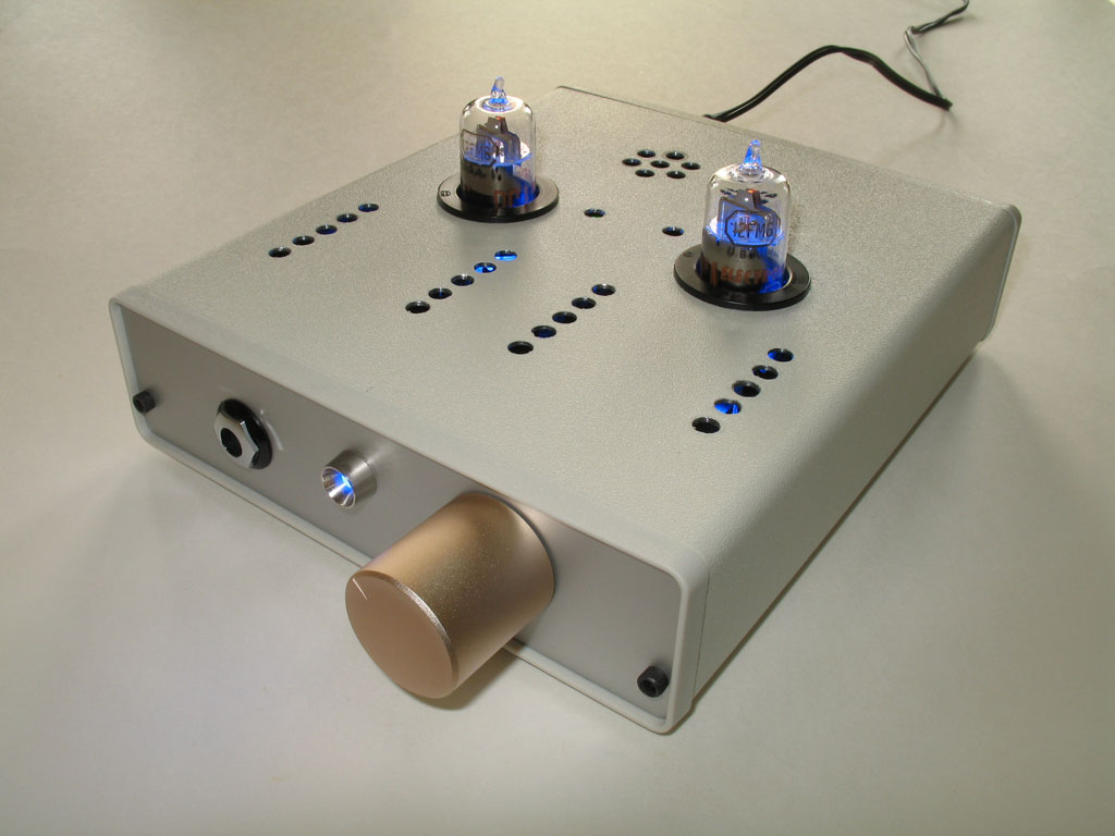
The finished amp in the Lansing "CT" case is shown at left. More details can be found on the Prototype menu selection at left. This amp proved to be as detailed as the first. As mentioned previously, Colin and I had discussed producing this board in quantity as a "miniature" MAX. However, Colin insisted that we investigate whether my sense was accurate that the old prototype MAX board was really more detailed or whether it was my imagination. Rather than attempt to conduct a double-blind study fiasco, he suggested that we find out what was going on with the ripple |
|
in the power supply of the two designs. We both agreed that might be the source of the difference. Along the way of having hundreds of users constructing the MAX, a couple had noted a slightly higher ripple measurement than desired. We had long suggested that the MAX's power supply was equivalent to the performance of Tangent's excellent STEPS power supply (no longer available). With the LM317, TO-220 rectifiers and 4000uf onboard capacitance, it was certainly designed and constructed to the same standards. However, those two users mentioned previously had suggested measurements of ~1mVAC for the MAX PS. By comparison, Tangent's TREAD power supply measures 0.060mVAC, with the STEPS very slightly better at 0.058mVAC. I confirmed for Colin that my own MAXes measured ~1mVAC on my best Fluke meter, but that both the old prototype MAX with the offboard rectifier string and caps and the newly constructed miniature MAX with board surgery measured 0.0mVAC on the Fluke. The problem with this kind of measurement, though, is that 1mVAC is the limit of measurement for most meters, including the Fluke. So, it could just as easily be 0.001 as it could be 0.999mVAC, with only the variance in the meter's precision resulting in any value inbetween. (Note that many multimeters are unable to measure true RMS for AC voltage, too. So, if you try this at home, be sure to measure with a quality multimeter at "Gnd" and "V+".) The answer was to build Tangent's LNMP, or Low Noise Measurement Preamplifier. The LNMP is actually constructed specifically for measuring power supply noise beyond the capability of multimeter. It actually pre-amplifies the AC ripple from the power supply output so that the noise and ripple is a large enough quantity for the multimeter to read with more precision. When this device is sandwiched between the multimeter and the amp's PS test points, it amplifies the noise/ripple by a factor of 1000. The 1mVAC limit of the Fluke becomes 1.000VAC. | |
 |
The LNMP finally allowed us to make some solid measurements to find out what was going on between the MAX and the miniature MAX prototypes. As it turned out, all of my MAXes measured about 800μVAC noise on the power supply, while the MiniMAX protos measured about 75μVAC. A bit higher than our STEPS goal, but still a magnitude difference between the MAX and the MiniMAX prototypes. The question now was what was causing it? Colin suspected that the output tantalum of the PS was conflicting with the high capacitance installed at the entry to the MAX circuit. |
|
In effect, there was 7200 uf of installed capacitance (4 x 1800uf for CR4 and CR5) immediately after the tiny output tantalum of the power supply, with only a short PCB trace of copper inbetween. At the same time, I suspected some issues with the ground plane connection perhaps still contaminated with AC. The ps trimmer and a couple of other parts were still located on the ground plane section of the MAX board. What resulted next was several weekends of trying one thing after another - focusing on removing the tantalum and installing a very small resistance. We tried resistors, inductors, even Nichrome wire in specific lengths (Nichrome has a definite resistance/length ratio). The focus was very small resistances of about 2 ohms down to fractional ohms. Plus, I tried a number of different surgeries around the ground plane on an existing MAX - actually making the ground plane into mince-meat on that particular MAX. What we found were two things: Neither scenario could equal the low noise of the MiniMAX early-prototypes, while a series resistance on those same prototypes appeared to reduce the noise to less than 0.040mVAC, quite outstanding. The conclusion actually surprised us: a ground plane was needed under the power supply to reduce noise further (me, mostly, because I still thought the ground plane was a problem - it was not). Colin designed a new MiniMAX prototype board, based on these results, and we proceeded to run a group testing for the prototypes with an initial run of 10 boards. Using the LNMP, we confirmed that the MiniMAX prototype board's power supply ground plane was indeed successful. Further testing with the LNMP resulted in the optimum series resistance between the power supply and the rest of the board. | |
|
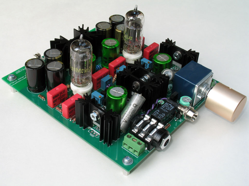
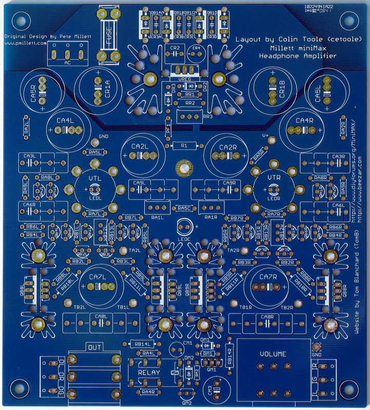
The actual production board is at right. Small changes were made between this board and the prototype: more cooling holes, wider pads at CA8, and the PolyFuse silkscreen was changed to "PF1" |
 |
|
We noted that the original MiniMAX prototypes that I had constructed both used a PolyFuse as the primary connection between the power supply and amp circuit. The PolyFuse was a legacy from the original Millett Hybrid design. Looking up the resistance of the PolyFuse revealed that it was actually about 0.5ohms - within the range of optimal for reducing PS noise. At the same time, we realized that the PolyFuse could also provide overcurrent protection for the buffer - something the buss fuse in back could never do (the buss fuse primarily protected the walwart used to supply the MAX). The result was the selection of the PolyFuse "PF1" as the series connector between the power supply and the rest of the MAX-circuit. This became the production MiniMAX board and is the basis of the design presented on this website. The production MiniMAX board, with a bit of further tweaking, results in a noise and ripple under a static load of 0.045mVAC. This is truly outstanding low noise performance. The MiniMAX Team believes that there exists no other onboard wall-powered power supply with this kind of performance outside of the MiniMAX. | |