www.beezar.com

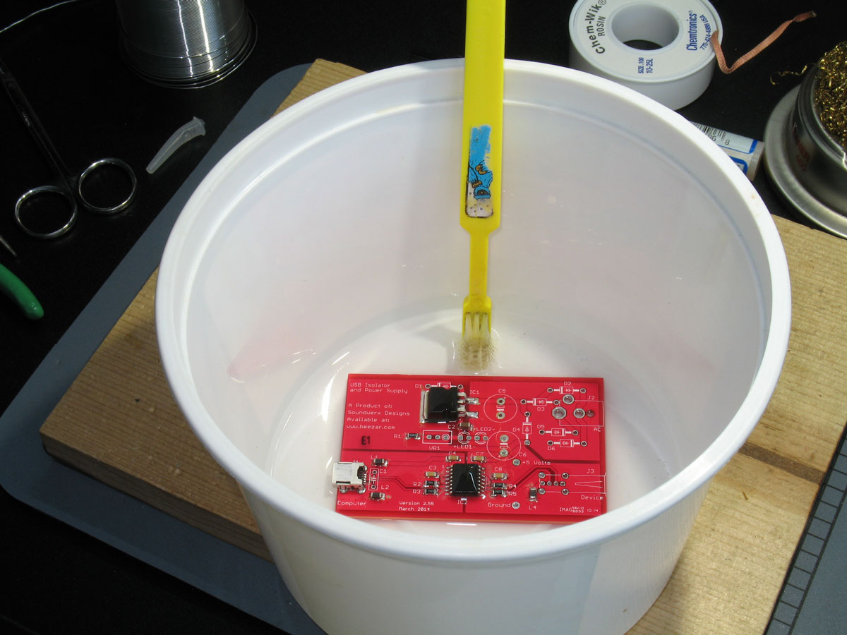
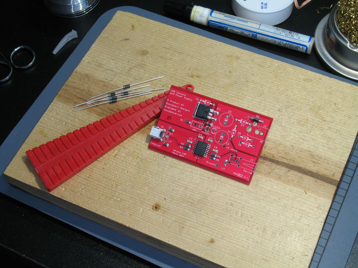
At this stage in populating the PCB, I usually go for a rinse. This cleans off the very sticky flux-pen residue. Plus, before you install any through-hole parts, scrubbing the PCB with alcohol (91% from Walmart) is quite easy. You can get the PCB thorougly clean from the flux-pen flux. Since the remaining parts are through-hole, there is very little flux added for the remainder of the parts - only that small amount of flux that comes from the solder itself. I still clean that, too - but it's quite a bit less than it would be otherwise. Here we see the diodes in preparation for bending the leads to the right length and installing them on the PCB. The handy-dandy resistor bending jig, or lead-bender, is an inexpensive and valuable tool for through-hole work. If all parts were the same, then PCB's could be designed for the exact length of through-hole parts. They aren't, though, so often times, the leads must be bent to some length beyond just bending at the ends of the part body. The resistor bending jig helps us do that neatly and cleanly:
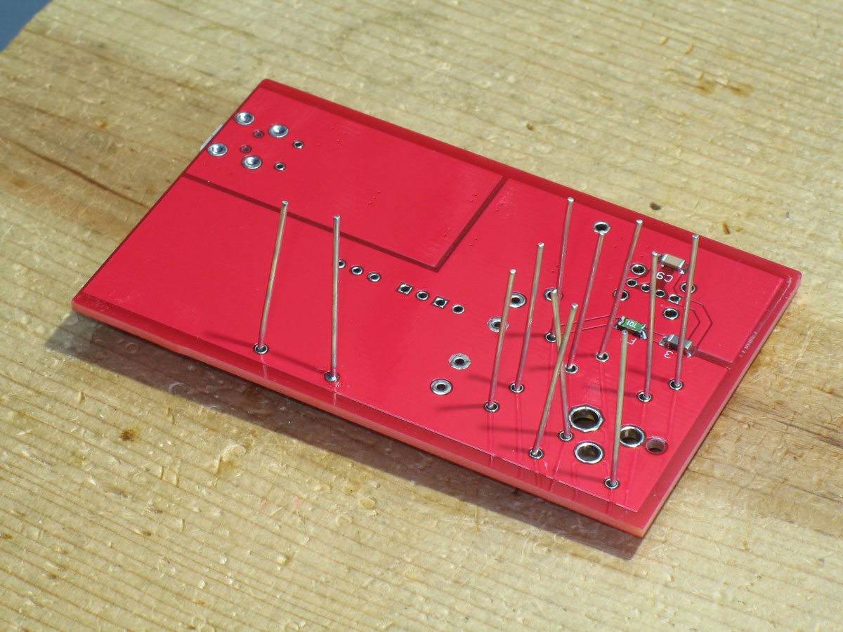
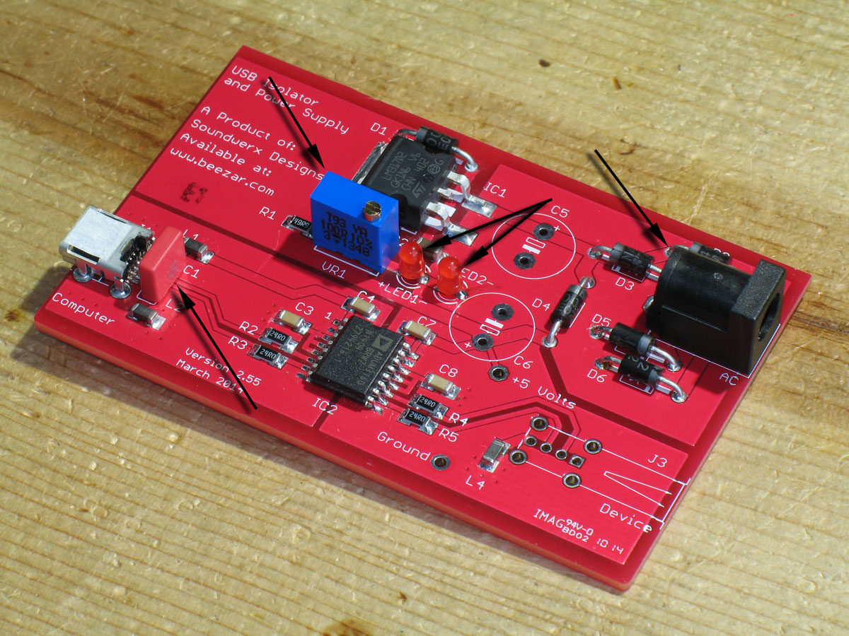
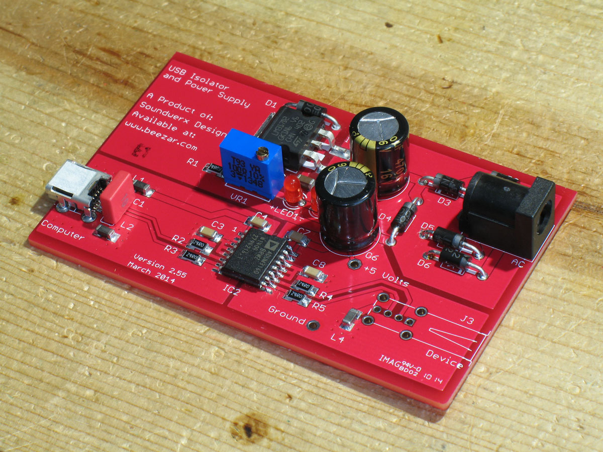
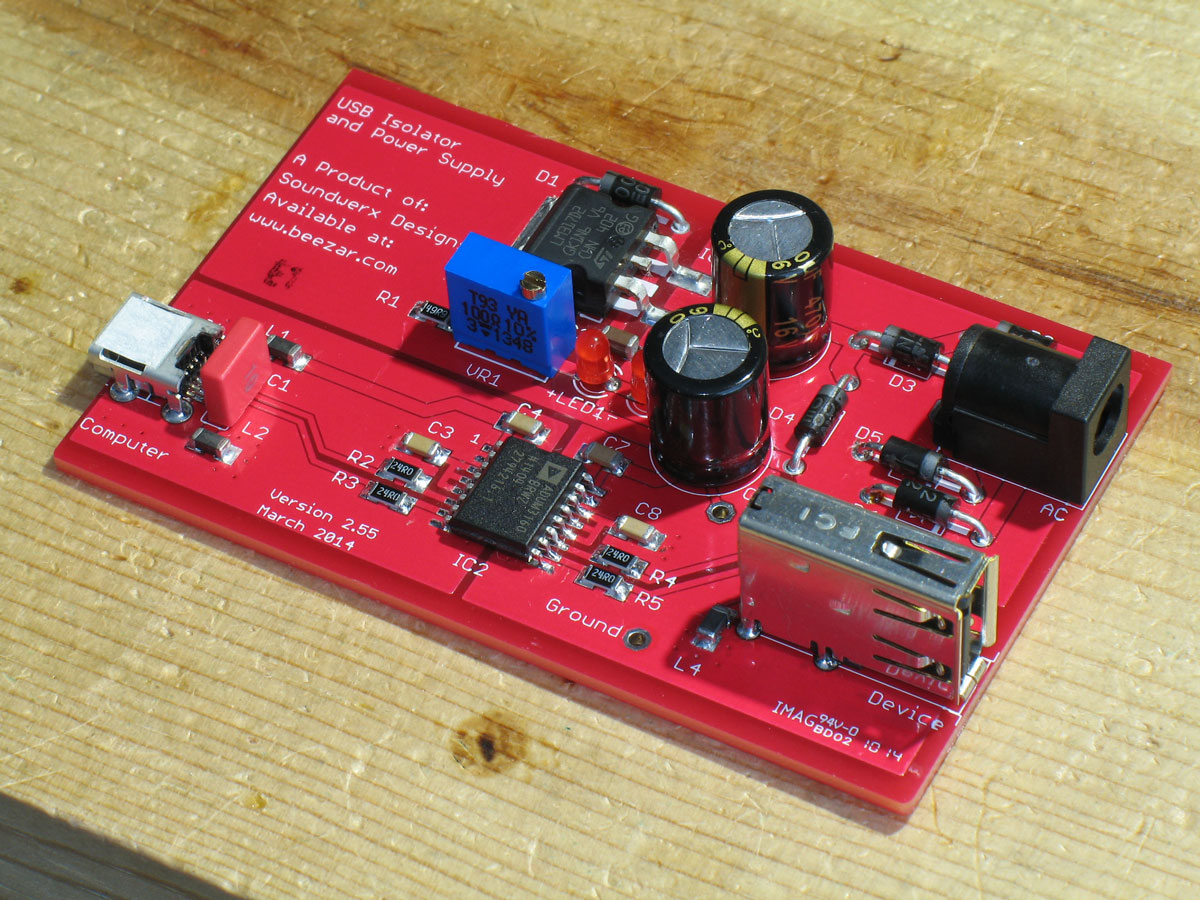
Here we have all of the diodes with their leads bent to the proper length, positioned into the proper locations on the PCB, and the PCB turned upside down. The reason for installing shorter parts first is that if you turn the PCB upside down on a flat surface, you can apply pressure to easily keep the parts flush to the surface of the PCB. If you went out of sequence as I did here, it's still possible to do that, but you have to be a little creative - either place something under the diodes or move the PCB to an edge on the building board so that the taller parts don't touch. Now that the diodes are installed, we can claim that we're back on track for a shortest-to-tallest parts sequence. Pictured here are the remainder of the the through hole parts lined up so that you can readily see the height differences. From left to right, in order of tallest to shortest, C5 & C6, J3 (pretty much the same as C5 & C6), J2, VR1, C1, and LED1 & LED2. Here we see a majority of the remaining through-hole parts installed. Both LED's (note the polarity - long lead is positive!!), then C1, and VR1 & J2 (more or less the same height once you include VR1's adjustment screw). Be careful in installing VR1. A trimmer such as this, while pretty standard for our DIY culture, nevertheless has very small pins. It can be easy to melt and damage it. Be sure that you solder one pin at a time, flip over the PCB and check the alighnment and whether it's flush to the PCB. Repeat until finished. Solder C5 and C6. Ensure their proper orientation. Finally, solder J3. Take your time in soldering J3. Check for proper alignment constantly while soldering. It's very easy to get the connector popped up in front or behind. The bottom tongue should be flush to the top surface of the PCB. Again, this is a connector that may have to endure some torque, so ensure that the frame pins (four of them) are soldereed completely and that you have some wicking to the top surface: Another angle: Whoa!! We've finished populating the PCB! Take a short break at this point to fully inspect the PCB. Make certain that you haven't forgotten to solder a remaining pad somewhere. Also, take this time to fully clean and rinse the PCB. (You may want to remove the small piece of protective tape that comes on the SMD mini-USB jack.) Refer to the setup page next for setting the voltage. Then come back for final assembly! |