|
STEP 6 - Apply Solder Anchor Pts for the TPS Regulators
Similar to the PCM chip, apply solder in preparation of anchoring both of the TPS regulators. The top left pin-pad seems the most convenient, but a different pad is OK as long as it allows you to rotate the chip to correct for small alignment errors once anchored.
|

|
STEP 7 - Solder the Remaining Pins of the TPS Regulators
Despite their small size, the TPS chips are very similar to soldering SOIC-8 opamps. The pins are far enough apart to allow you to solder one pin at a time. If you prefer, you can clean the joints up for a professional-looking appearance with a roll and wipe with a clean soldering tip. |
Please note which TPS regulator goes where!!
|

|
At this point, your board and chip should look like the photo at left - the TPS regulators are installed. Again, it looks pretty rough, but don't worry about cleaning it up at this point. You should be able to easily see that the TPS regulator pins are correctly soldered. If not, then clean it up until you are certain. Otherwise, proceed on with the remainder of the SMD parts below.
|

|
STEP 8 - Apply Solder Anchor Pts for the SMD Passive Parts
Finally! This is where SMD soldering gets fun. A great method is to apply solder to one pad for each of the remaining SMD parts on the top of the board - SMD capacitors, resistors, and ferrites ("L" parts). Leave the C3 pads blank. You'll apply solder to C3's right pad in the step below. After that, we'll finish them all in Steps 9 and 10.
|
NOTE: Pay close attention to the layout! Many of the parts are oriented in different directions - that looks confusing as to which pad goes where. Refer to the layout often to prevent confusion in this regard.
|
|

(Click for a large pic.)
|
STEP 8a - Solder the PCM Pin 18's trace (4th pin from bottom right) to the C3 right pad
This is design defect in the board. Scrape the green mask from the Pin 18 trace and solder to C3's right pad. These two traces must be connected. Or, thought of another way - the trace coming from the 4th pin from the bottom right must be connected to Ground.
|
|

|
STEP 9 - Solder the PCM Decoupling Capacitors First
Generally speaking, you want to solder from the center of the board out. Following this strategy, solder the capacitors C1 through C6 that are closest to the PCM pins.
|
The technique is fairly simple. Hold your soldering iron to melt the solder on the anchor pad. Then with your tweezers, move the part to the pad. Release the soldering iron, then release the tweezers when the solder has cooled. You can solder the other side of the parts now in a normal fashion, or do it all at once when you get the rest of the parts on the board. These might be better to finish completely since they are so close to the PCM chip.
|

|
STEP 10 - Solder the Remaining SMD Parts
Finish up by soldering the rest of the SMD parts. Take note of C16 when using the TPS chips. R7 and R8 are not used, and C16 goes on the pads for R8. Also, C11 and C13 have dual pads for electrolytic or SMD capacitors. The TPS regulators only use the SMD capacitors.
|
On the other hand, if you have REG101 regulators, then you will need to populate C11 and C13 with electrolytic capacitors. R7 and R8 will need to be selected (refer to the BOM) to adjust the REG101 in the 4.75V position.
|

|
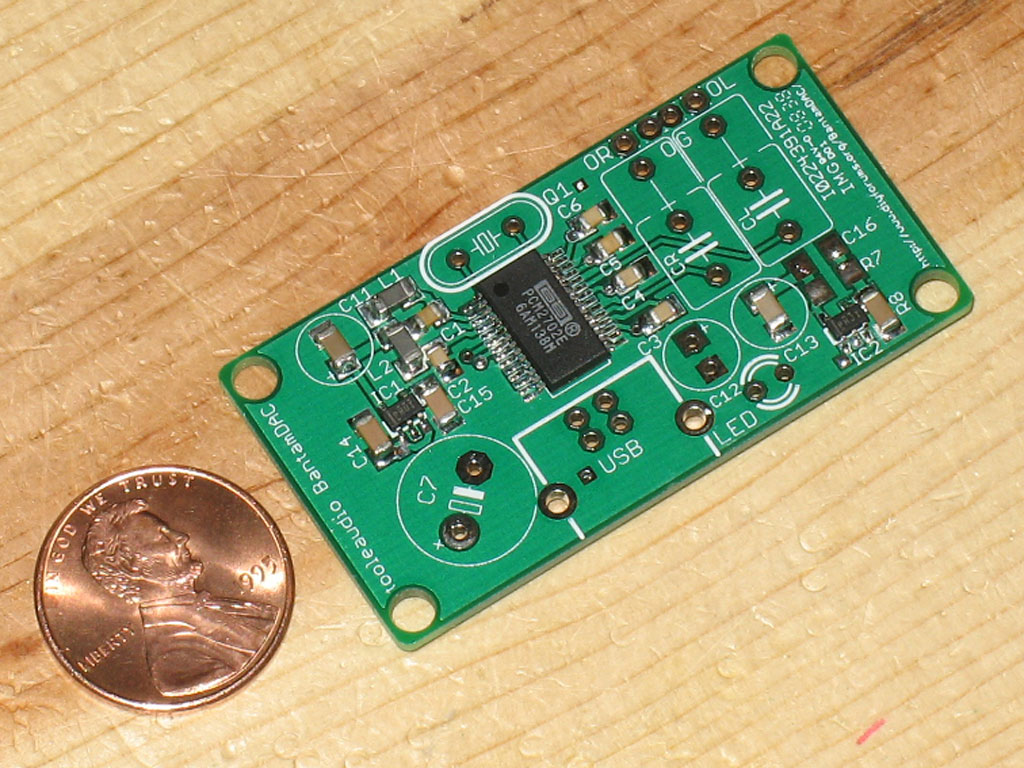
Here we see a finished top, except for the through-hole parts. Don't add anything else to the topside at this point. Instead, we'll flip the board over and continue work on the bottom.
|